Disclaimer: This information is provided as-is for the benefit of the Community. Please contact Sophos Professional Services if you require assistance with your specific environment.
Table of Contents
Overview
This recommended read describes configuring BGP routing over a Route-Based VPN (RBVPN) tunnel using the Sophos Firewall with SFOS version 18. This procedure will work between two Sophos Firewall devices and a third-party network device if it supports RBVPN.
Note: This article does not provide in-depth information regarding BGP, RBVPN, or firewall technologies.
This applies to the following Sophos products and versions
Sophos Firewall version 18 and onwards
Scenario
Establish BGP routing via RBVPN tunnel between the Head Office (HO) and the Branch Office (BO).
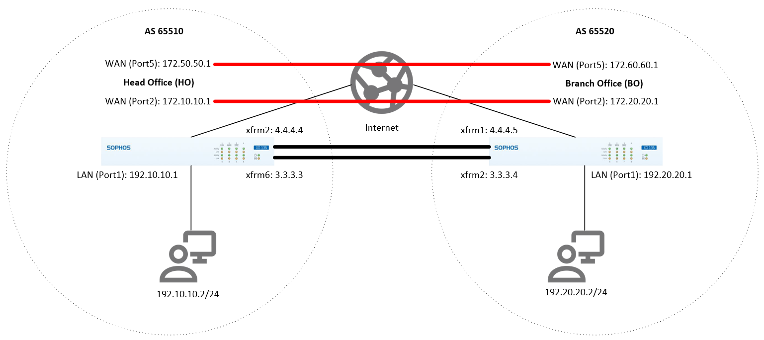
Head Office (HO) configuration
The configurations provided here are just an example. You can configure it according to your organization's networks and requirements.
Configure the RBVPN tunnel
- Go to VPN > IPsec connections. Under the IPsec Connections section, click Add and configure the RBVPN connection, as shown below.
The Listening interface is the HO's WAN IP, and the Gateway address is the BO's WAN IP. For Version 19 onwards, go to CONFIGURE>Site-to-site VPN>Ipsec then click Add.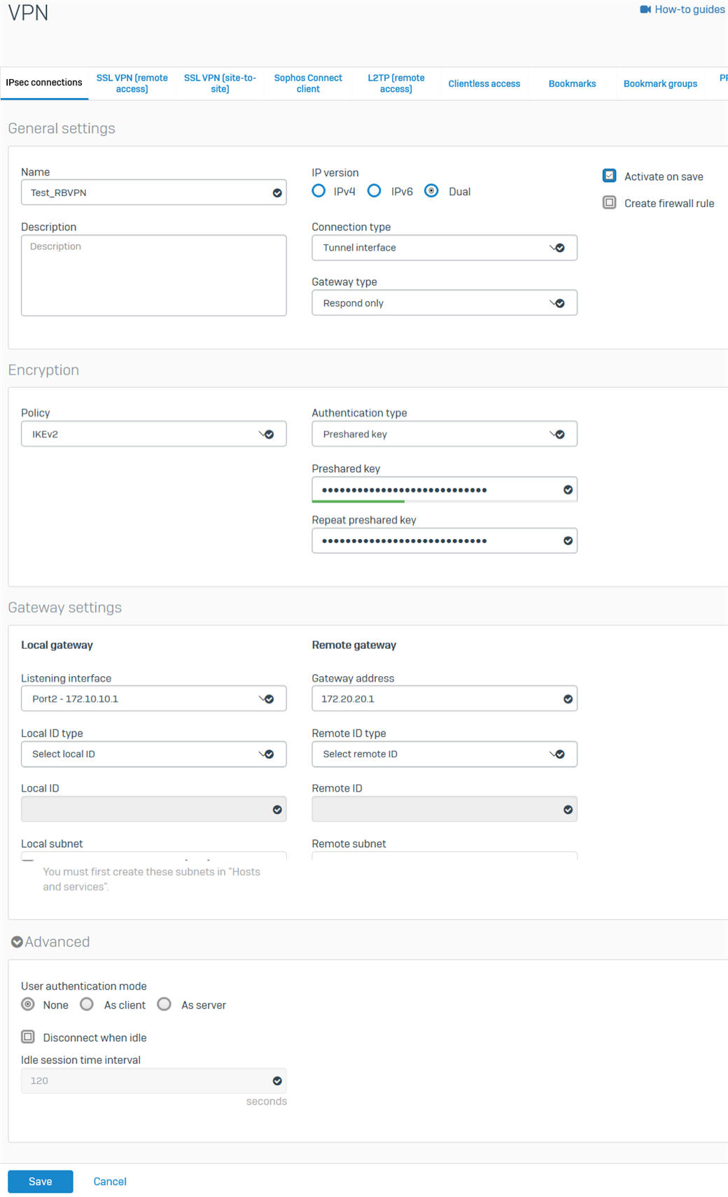
- Click Save. The RBVPN will be automatically activated and will create an interface named xfrm followed by a number.
- Go to Network > Interfaces and click the xfrm interface that was created. In this example, it’s xfrm6.
- Enter the virtual IP address for this interface and then click Save.
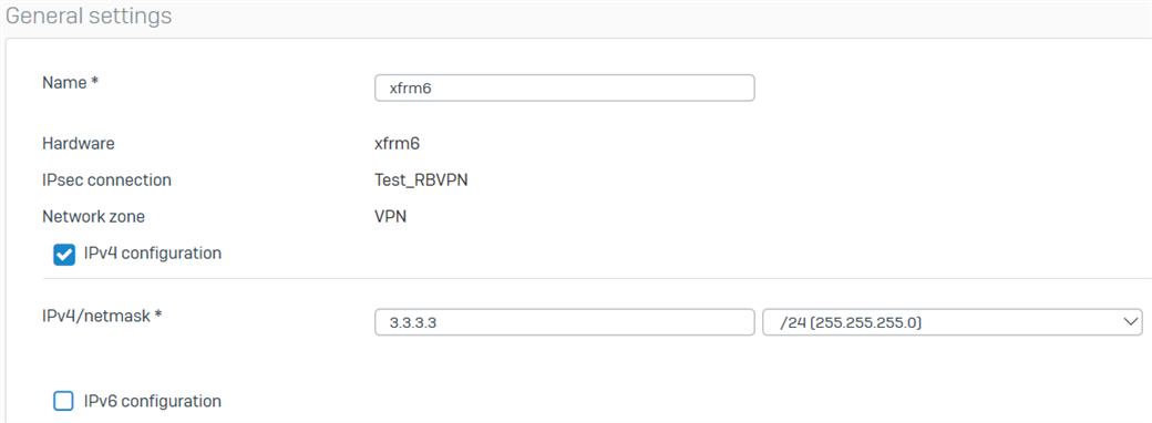
- Repeat the procedure above to create another RBVPN tunnel using the other WAN interfaces of the HO and BO, respectively. In this example, the other xfrm interface that was created is xfrm2.
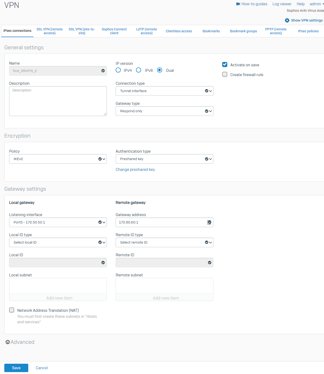
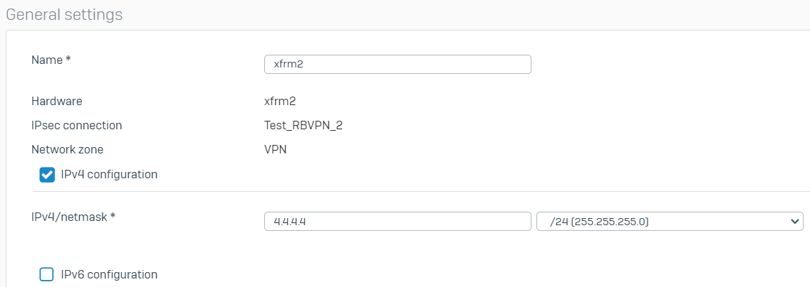
There should now be two RBVPN connections.
Configure the firewall rules
- Go to Rules and Policies> Firewall rules > Add firewall rule > New firewall rule. Configure the inbound firewall rule as shown below.
For the Source networks and devices and Destination networks, enter the BO's LAN networks and the HO's LAN networks, respectively. You can also create host definitions by clicking Add new item.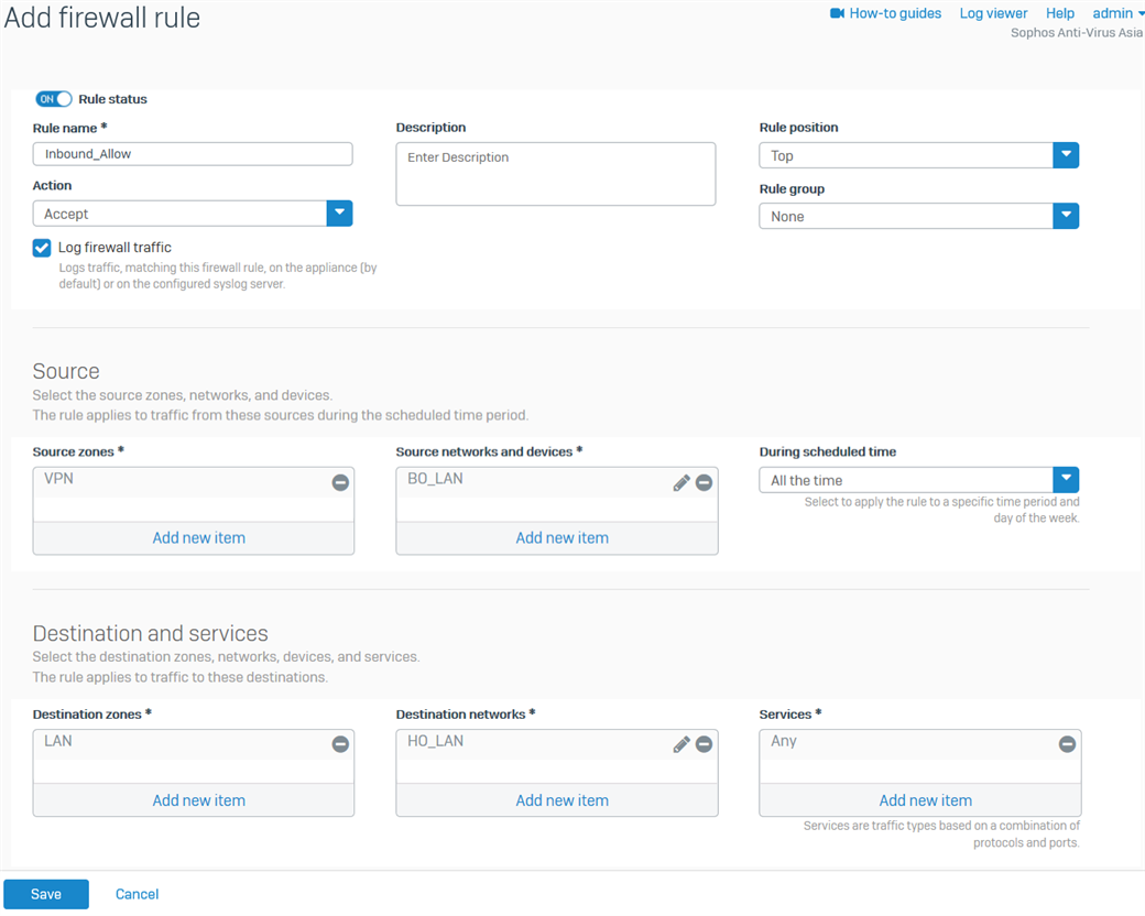
- Click Save.
- Create another firewall rule for the outbound traffic, as shown below.
For the Source networks and devices and Destination networks, enter the HO's LAN networks and the BO's LAN networks, respectively. You can also create host definitions by clicking Add new item.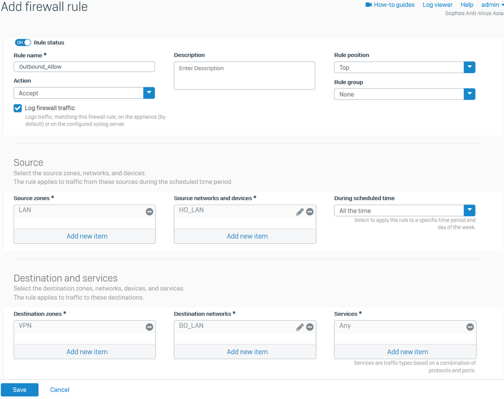
- Click Save.
Configure the device access
- Go to Administration > Device access and enable Ping/Ping6 and Dynamic Routing for the VPN Zone.
- Click Apply.
Branch Office (BO) configuration
Configure the RBVPN tunnel
- Go to VPN > IPsec connections. Under the IPsec Connections section, click Add and configure the RBVPN connection, as shown below.
The Listening interface is the BO's WAN IP, and the Gateway address is the HO's WAN IP. For Version 19 onwards, go to CONFIGURE>Site-to-site VPN>Ipsec, then click Add.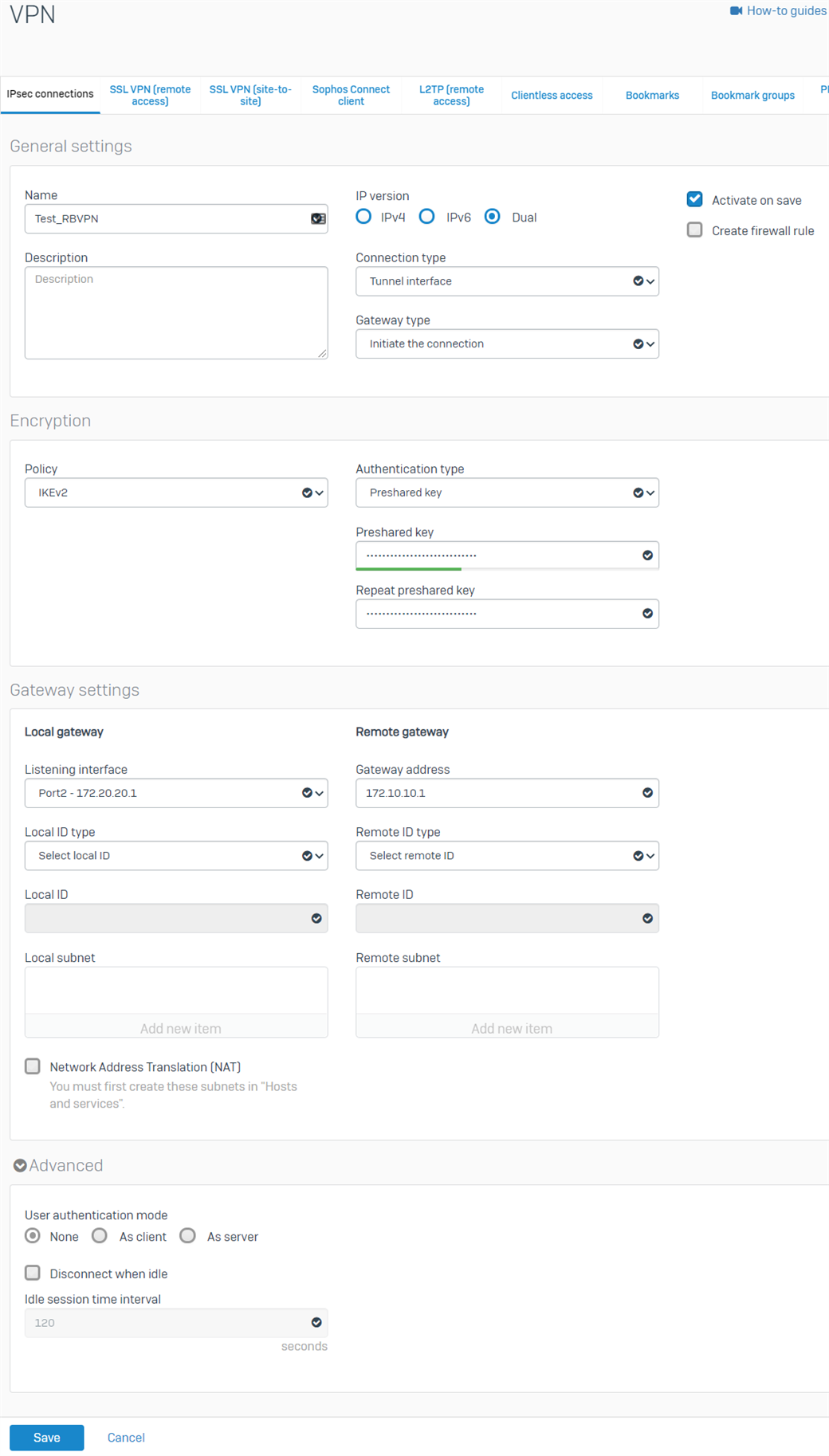
- Click Save. The RBVPN will be automatically activated and will create an interface named xfrm followed by a number.
- Go to Network > Interfaces and click the xfrm interface that was created. In this example, it is xfrm2.
- Enter the virtual IP address for this interface and then click Save.
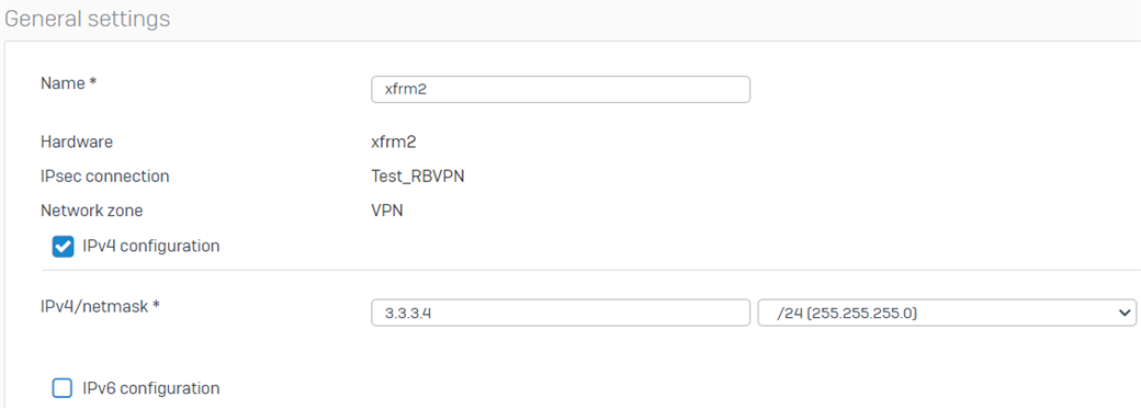
- Repeat the procedure above to create another RBVPN tunnel using the other WAN interfaces of the HO and BO, respectively. In this example, the other xfrm interface that was created is xfrm1
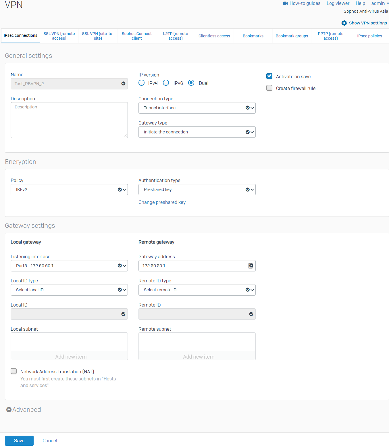
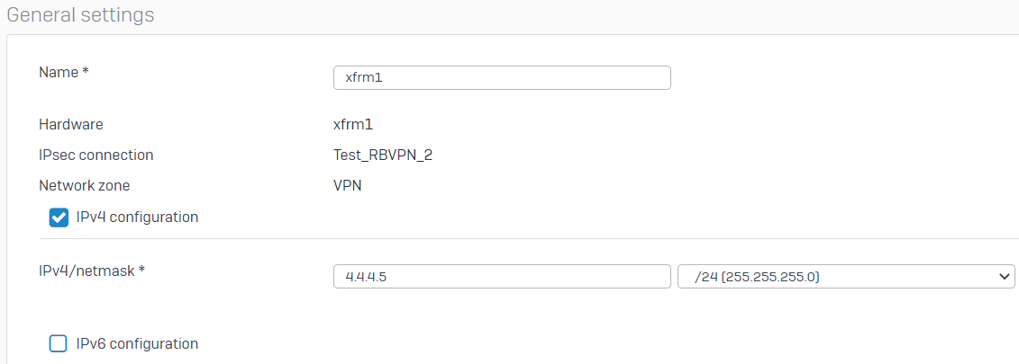
.There should now be two RBVPN connections.
Configure the firewall rules
- Go to Rules and Policies > Firewall rules > Add firewall rule > New firewall rule. Configure the inbound firewall rule as shown below.
For the Source networks and devices and Destination networks, enter the HO's LAN networks and the BO's LAN networks, respectively. You can also create host definitions by clicking Add new item.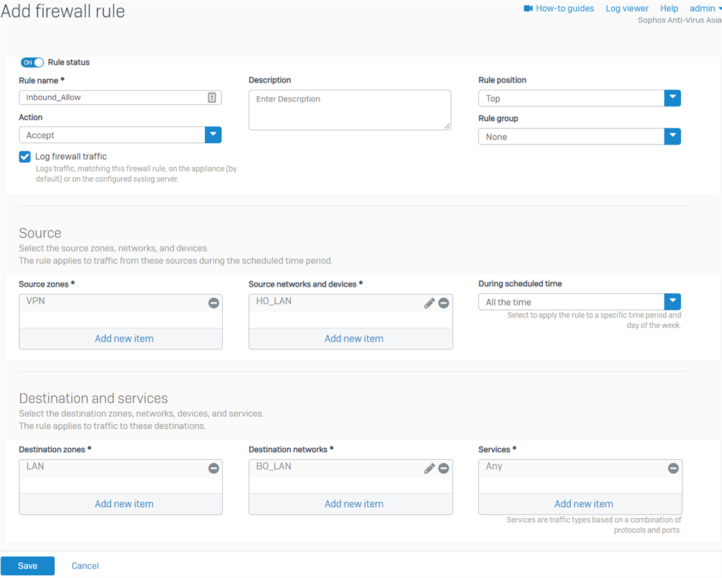
- Click Save.
- Create another firewall rule for the outbound traffic, as shown below.
For the Source networks and devices and Destination networks, enter the BO's LAN networks and the HO's LAN networks, respectively. You can also create host definitions by clicking Add new item.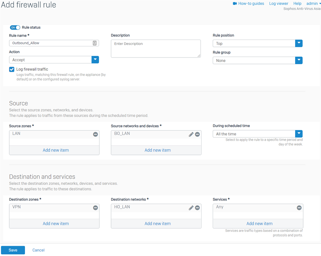
- Click Save.
Configure the device access
- Go to Administration > Device access and enable Ping/Ping6 and Dynamic Routing for the VPN Zone.
- Click Apply.
BGP configuration
Head office
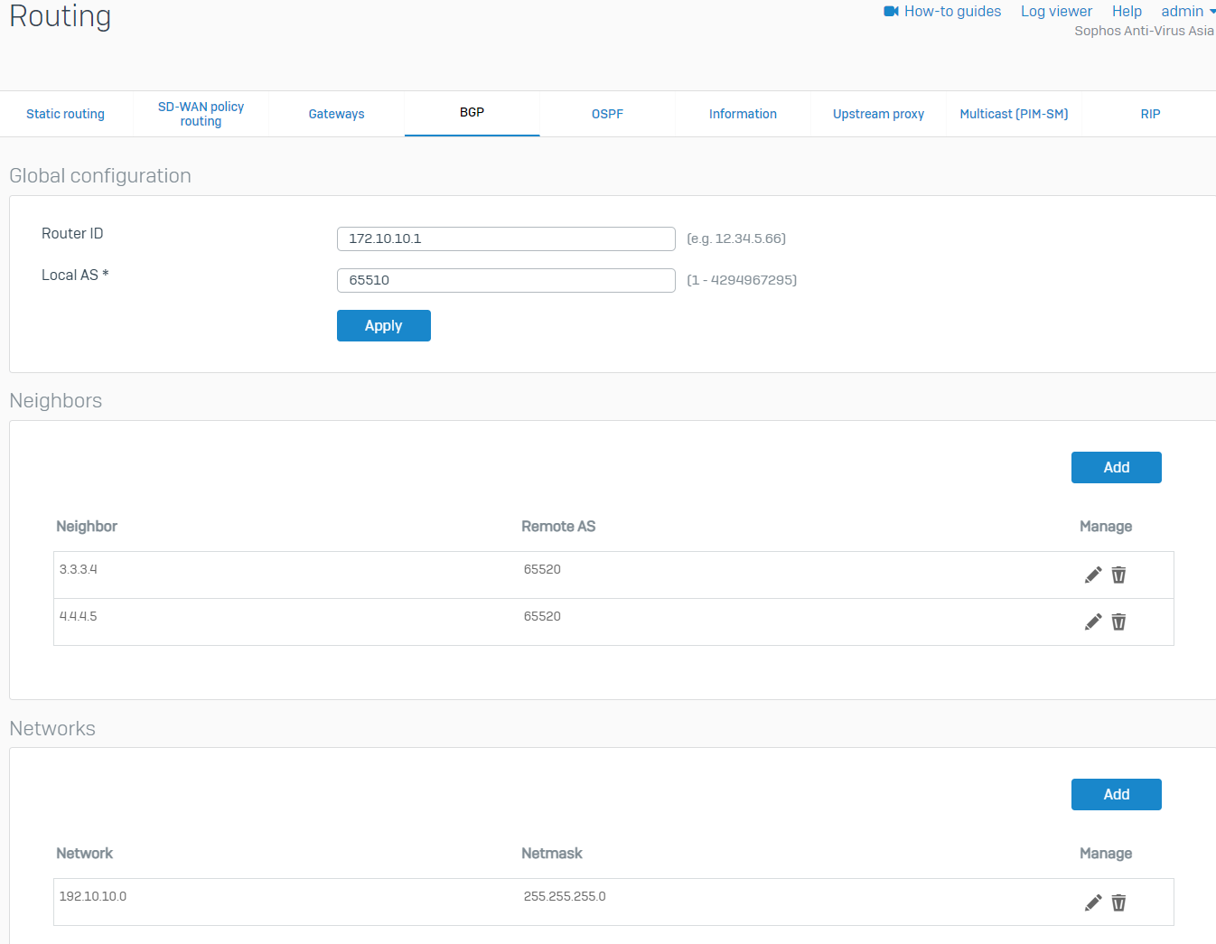
- Go to Routing > BGP. Enter any IP for the Router ID and enter the Local AS of the HO. We'll use the HO's WAN IP as the Router ID in this example. Click Apply, then click OK when prompted.
- Under the Neighbors section, click Add. Enter the IP address of the BO's xfrm interfaces and AS number, and then click Save. Create another one for the other xfrm interface of the BO.
BO xfrm1 Parameter Value IPv4 address 4.4.4.5 Remote AS 65520 BO xfrm2 Parameter Value IPv4 address 3.3.3.4 Remote AS 65520 - Under the Networks section, click Add. Enter the HO's LAN and click Save.
Configure the maximum path
- Sign in to the HO's CLI and go to 3. Route Configuration > 1. Configure Unicast Routing > 3. Configure BGP.
- Run the following commands. Use the HO's AS number. The maximum paths can be configured according to your network requirements.
bgp> enable
bgp# configure terminal
bgp(config)# router bgp <AS number>
bgp(config-router)# maximum-paths <number>
bgp(config-router)# write
bgp(config-router)# exit
bgp(config)# exit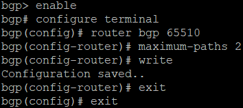
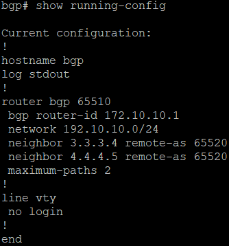
- Verify the configuration by running the command show running-config.
Branch office
- Go to Routing > BGP. Enter any IP for the Router ID and enter the Local AS of the BO. We'll use the BO's WAN IP as the Router ID in this example. Click Apply, then click OK when prompted.
- Under the Neighbors section, click Add. Enter the IP address of the HO's xfrm interfaces and AS number, then click Save. Create another one for the other xfrm interface of the HO.
HO xfrm2 Parameter Value IPv4 address 4.4.4.4 Remote AS 65510 HO xfrm6 Parameter Value IPv4 address 3.3.3.3 Remote AS 65510 - Under the Networks section, click Add. Enter the BO's LAN and click Save.
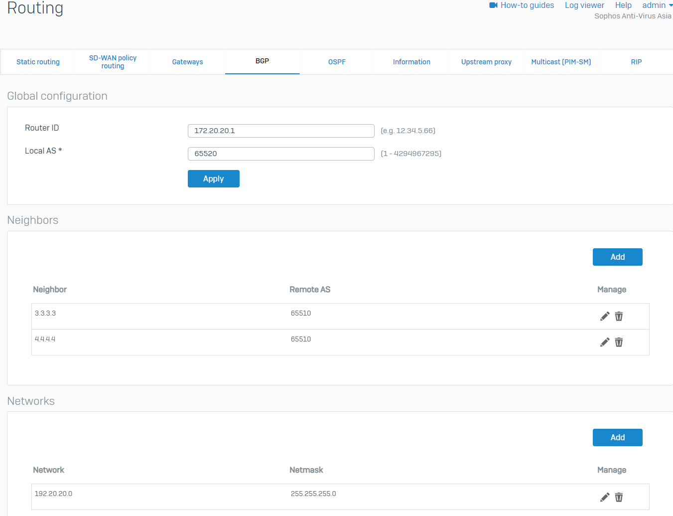
Configure the maximum path
- Sign in to the BO's CLI and go to 3. Route Configuration > 1. Configure Unicast Routing > 3. Configure BGP.
- Run the following commands. Use the BO's AS number. The maximum paths can be configured according to your network requirements.
bgp> enable
bgp# configure terminal
bgp(config)# router bgp <AS number>
bgp(config-router)# maximum-paths <number>
bgp(config-router)# write
bgp(config-router)# exit
bgp(config)# exit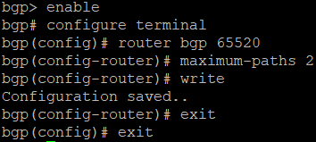
- Verify the configuration by running the command show running-config.
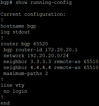
Verification
RBVPN
- In the BO Sophos Firewall, go to VPN > IPsec connections and enable the created tunnels by clicking the red button under the Connection column. It should turn green, meaning that the RBVPN tunnels have been established.

BGP
- Sign in to the CLI of the HO XG Firewall as an administrator.
- Select 3. Route Configuration > 1. Configure Unicast Routing > 2. Configure BGP.
- Enter the following commands:
bgp> enable
bgp# show ip bgp
bgp# show ip bgp neighbors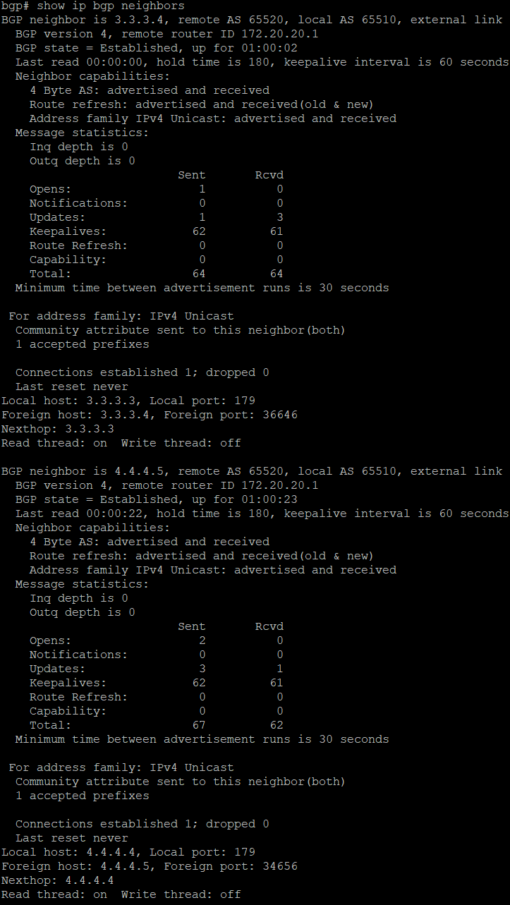
bgp# show ip bgp summary
- Go to 5. Device Management > 3. Advanced Shell.
- Enter the following command to see that the routes have been advertised.
route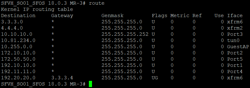
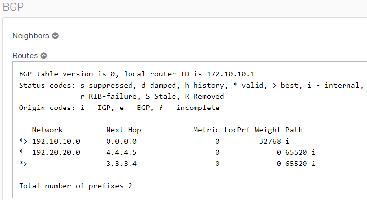
- BGP can also be verified in the Webadmin by going to Routing > Information.
Traffic flow
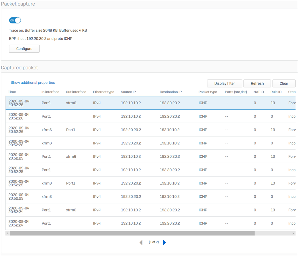
- Go to Diagnostics > Packet capture from the HO XG Firewall and click Configure.
- Enter the following as the BPF string, then turn ON the packet capture.
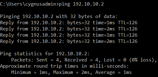
host 192.20.20.2 and proto ICMP - From the host 192.20.20.2 in the Branch Office, ping the host 192.10.10.2 in the Head Office.
- The following will be displayed in the packet capture. It shows that the traffic is going in and out of the xfrm6 interface, the RBVPN tunnel. Traffic can also be checked in the Log Viewer.
Related information
Updated Links to latest
[edited by: Raphael Alganes at 12:45 PM (GMT -8) on 17 Dec 2024]


