

Disclaimer: This information is provided as-is for the benefit of the Community. Please contact Sophos Professional Services if you require assistance with your specific environment.
______________________________________________________________________________________________________________________________________
Table of Contents
Overview
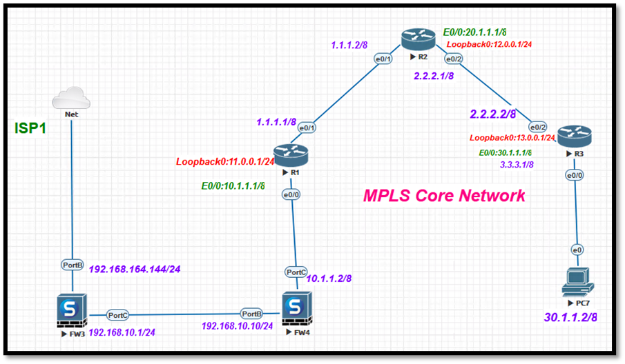
This configuration shows the MPLS traffic from the Cisco router via the Sophos firewall.
As there’s no specific configuration for MPLS on the Sophos Firewall, we need to use static routes to relay the traffic over the internet.
Topology
In this topology, we can see that two Sophos firewalls are connected and behind that, Cisco routers on which MPLS is configured.
Sophos Firewall Configuration
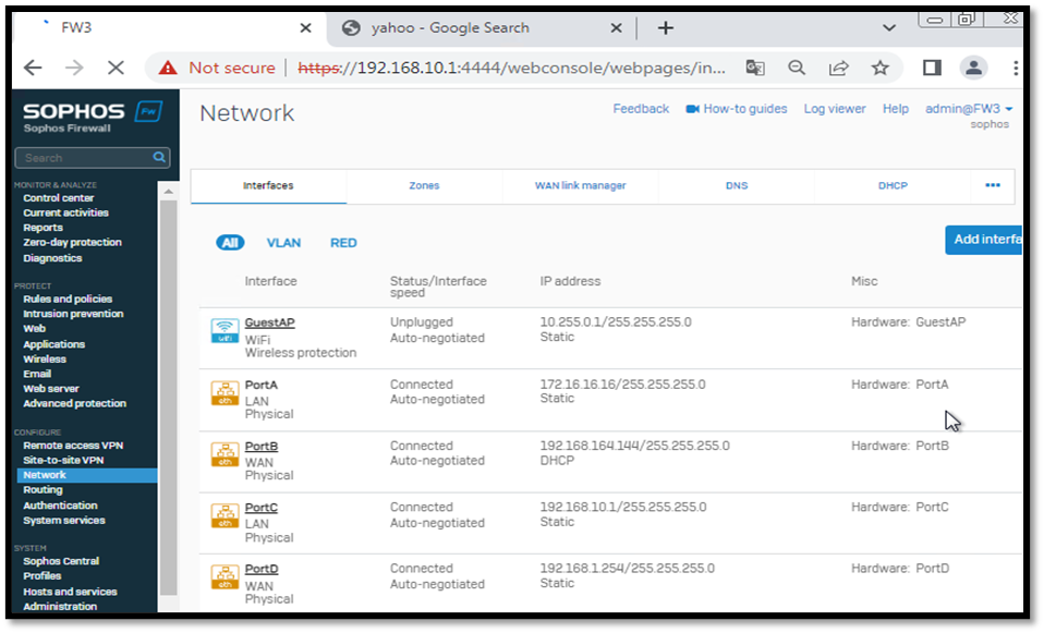
Step 1: Now ensure the port configuration is correct on the interface on the firewall (FW3). As we can see, PortB and PortC for LAN and WAN, respectively, as shown in the screenshot below:
Path: Network > Interfaces
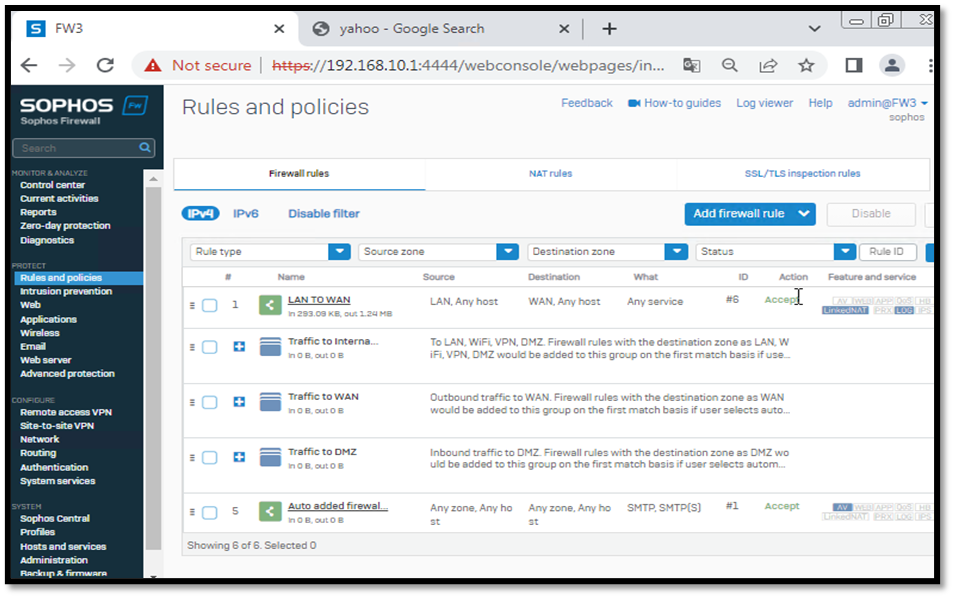
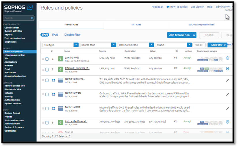
Step 2: Now we need to create a LAN to WAN rule without MASQ Nat on Firewall (FW3) as shown below:
Path: Rules and Policies > Firewall rules > Add firewall rule > New firewall rule:
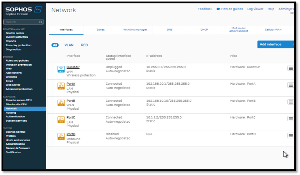
Step 3: We need to ensure the port configuration is correct on the interface on another firewall (FW4). As we can see, PortC and PortB for LAN and WAN, respectively, as shown in the screenshot below:
Path: Network > Interfaces
Step 4: Now create LAN to WAN rule without MASQ Nat on the firewall (FW4) as same created on FW3:
Path: Rules and Policies > Firewall rules > Add firewall rule > New firewall rule:
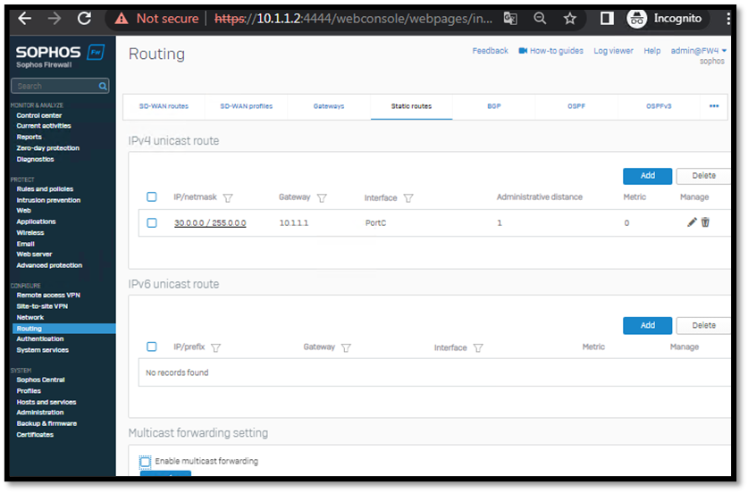
Step 5: Now, the next portion of the configuration is to add Static routes on the firewall (FW4) for network 30.0.0.0/8 for gateway 10.1.1.1 as shown in the screenshot below:
Cisco Router Configuration
Step 6: Now, make sure MPLS is configured properly on Cisco routers. Configuration is shown below on all three routers:
- Router-1
Below is the OSPF and MPLS config on Cisco R1
R1#show running-config
Building configuration...

Current configuration : 1168 bytes
!
version 15.4
service timestamps debug datetime msec
service timestamps log datetime msec
no service password-encryption
!
hostname R1
!
boot-start-marker
boot-end-marker
!
aqm-register-fnf
!
!
no aaa new-model
mmi polling-interval 60
no mmi auto-configure
no mmi pvc
mmi snmp-timeout 180
!
!
!
!
no ip domain lookup
ip cef
no ipv6 cef
!
multilink bundle-name authenticated
mpls label range 100 199
mpls label protocol ldp
!
!
redundancy
!
interface Loopback0
 ip address 11.0.0.1 255.255.255.0
!
interface Ethernet0/0
 ip address 10.1.1.1 255.0.0.0
!
interface Ethernet0/1
 ip address 1.1.1.1 255.0.0.0
 mpls ip
!
interface Ethernet0/2
 no ip address
 shutdown
!
interface Ethernet0/3
 no ip address
 shutdown
!
router ospf 1
 network 1.0.0.0 0.255.255.255 area 0
 network 10.0.0.0 0.255.255.255 area 0
 network 11.0.0.0 0.0.0.255 area 0
!
ip forward-protocol nd
!
!
no ip http server
no ip http secure-server
ip route 0.0.0.0 0.0.0.0 10.1.1.2
!
!
!
mpls ldp router-id Loopback0
!
control-plane
!
!
line con 0
 logging synchronous
line aux 0
line vty 0 4
 login
 transport input none
!
!
end

R1#
- Router-2
Below is the OSPF and MPLS config on Cisco R2
R2#show running-config
Building configuration...

Current configuration : 1219 bytes
!
version 15.4
service timestamps debug datetime msec
service timestamps log datetime msec
no service password-encryption
!
hostname R2
!
boot-start-marker
boot-end-marker
!
aqm-register-fnf
!
!
no aaa new-model
mmi polling-interval 60
no mmi auto-configure
no mmi pvc
mmi snmp-timeout 180
!
no ip domain lookup
ip cef
no ipv6 cef
!
multilink bundle-name authenticated
mpls label range 200 299
mpls label protocol ldp
!
!
redundancy
!
!
interface Loopback0
 ip address 12.0.0.1 255.255.255.0
!
interface Ethernet0/0
 ip address 20.1.1.1 255.0.0.0
!
interface Ethernet0/1
 ip address 1.1.1.2 255.0.0.0
 mpls ip
!
interface Ethernet0/2
 ip address 2.2.2.1 255.0.0.0
 mpls ip
!
interface Ethernet0/3
 no ip address
 shutdown
!
router ospf 1
 network 1.0.0.0 0.255.255.255 area 0
 network 2.0.0.0 0.255.255.255 area 0
 network 12.0.0.0 0.0.0.255 area 0
 network 20.0.0.0 0.255.255.255 area 0
!
ip forward-protocol nd
!
!
no ip http server
no ip http secure-server
ip route 0.0.0.0 0.0.0.0 1.1.1.1
!
!
!
mpls ldp router-id Loopback0
!
control-plane
!
line con 0
 logging synchronous
line aux 0
line vty 0 4
 login
 transport input none
!
!
end

R2#
- Router-3
Below is the OSPF and MPLS config on Cisco R3
R3#show running-config
Building configuration...

Current configuration : 1214 bytes
!
version 15.4
service timestamps debug datetime msec
service timestamps log datetime msec
no service password-encryption
!
hostname R3
!
boot-start-marker
boot-end-marker
!
aqm-register-fnf
!
!
no aaa new-model
mmi polling-interval 60
no mmi auto-configure
no mmi pvc
mmi snmp-timeout 180
!
!
no ip domain lookup
ip cef
no ipv6 cef
!
multilink bundle-name authenticated
mpls label range 300 399
mpls label protocol ldp
!
!
redundancy

!
interface Loopback0
 ip address 13.0.0.1 255.255.255.0
!
interface Ethernet0/0
 ip address 30.1.1.1 255.0.0.0
 mpls ip
!
interface Ethernet0/1
 no ip address
 shutdown
!
interface Ethernet0/2
 ip address 2.2.2.2 255.0.0.0
 mpls ip
!
interface Ethernet0/3
 no ip address
 shutdown
!
router ospf 1
 network 2.0.0.0 0.255.255.255 area 0
 network 3.0.0.0 0.255.255.255 area 0
 network 13.0.0.0 0.0.0.255 area 0
 network 30.0.0.0 0.255.255.255 area 0
!
ip forward-protocol nd
!
!
no ip http server
no ip http secure-server
ip route 0.0.0.0 0.0.0.0 2.2.2.1
!
!
!
mpls ldp router-id Loopback0
!
control-plane
!
line con 0
 logging synchronous
line aux 0
line vty 0 4
 login
 transport input none
!
!
end

R3#
Testing
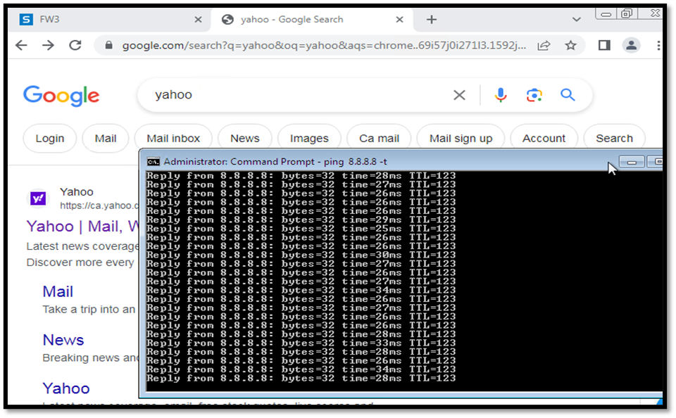
Step 7: Testing; in this step, we can see that PC7 is now able to access the internet and PC7 can ping 8.8.8.8 as shown below in two screenshots:
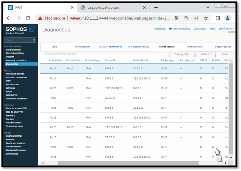
Step 8: We can see the traffic flow on the firewall (FW4), which is coming from Cisco routers via MPLS routes in Sophos GUI, as shown below:
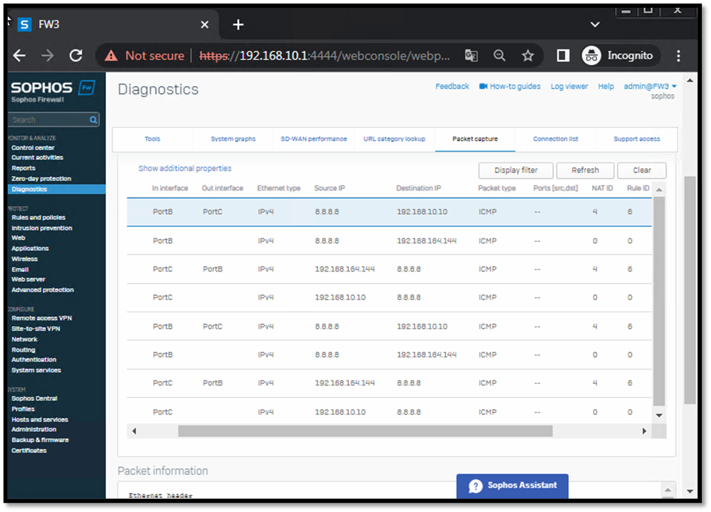
Step 9: We can see the traffic flow on the firewall (FW3), which is coming from the firewall (FW4) and routed to the internet using the created LAN to WAN rule.
______________________________________________________________________________________________________________________________________
Updated Grammar.
[edited by: Raphael Alganes at 11:00 AM (GMT -7) on 8 Oct 2024]