

Disclaimer: This information is provided as-is for the benefit of the Community. Please contact Sophos Professional Services if you require assistance with your specific environment.
Table of Contents
Overview
This Recommended read describes a best practice guide for building connectivity between multiple connections using high failover and zero downtime approaches, with real-world scenarios and examples.
We’re expanding on the new and old features of SFOS (Sophos Firewall OS) and how to use them to modernize network connectivity. This guide gives guidelines on building up and scaling your network. Your specific configuration may change.
In case of larger deployments, Sophos Central Orchestration can automate all steps in this guide. However, for customization and learning reasons, we wanted to highlight the entire configuration within the guide.
Product and Prerequisites
- Read-write permissions on the SFOS web admin for the relevant features.
- Version 19.5 above and no explicit subscription required
- Version 20 was used in the following guide
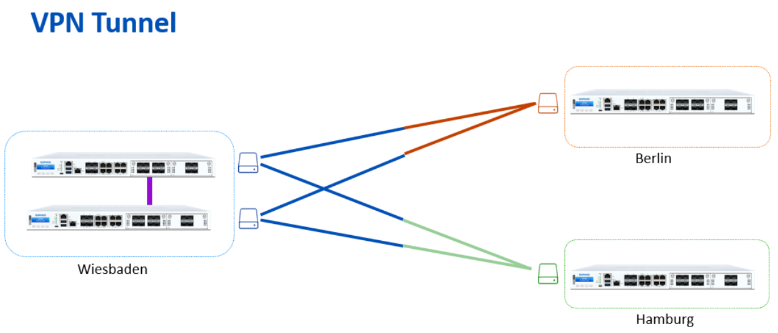
Network Diagram
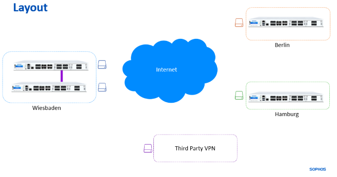
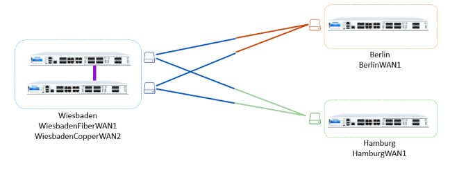
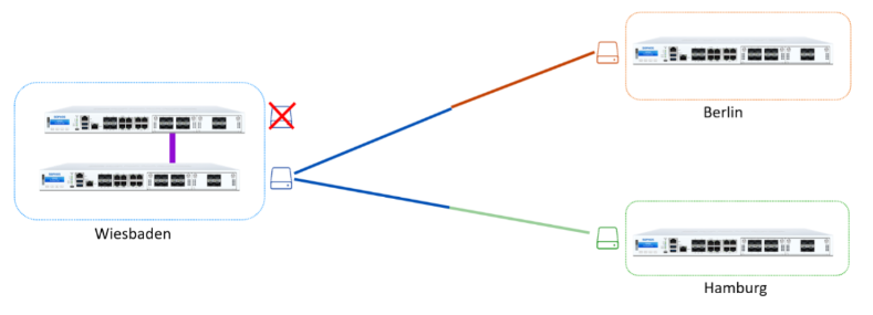
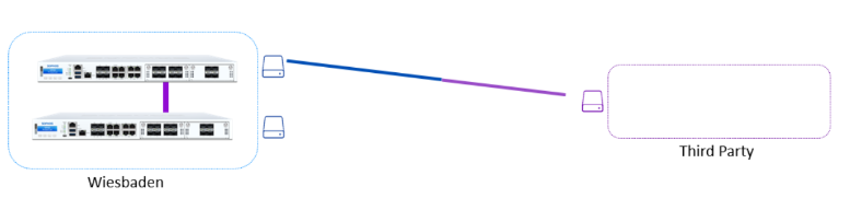
We build an example network to showcase the network diagram and features working.
- Wiesbaden is our HQ with Dual WAN connectivity.
- Berlin and Hamburg are our branch offices with a single WAN.
- We use a star topology, and all locations connect to our HQ.
Additionally, we’re connecting to a Third-Party VPN Site, which is our responsibility.
Best Practice: Use the location name as the hostname for the SFOS Appliance to differentiate the web admin consoles during configuring.
Note: On the following screenshots, we’re moving between Wiesbaden and Hamburg. The Hostname will be reflected on the top right corner.
Configuration
VPN
Our goal in the VPN section is to fully utilize both WAN connections.
We will use a Route-Based VPN approach with XFRM interfaces to utilize 4 tunnels. Each Location will build 2 tunnels.
For example, we will go through the configuration of one of the tunnels.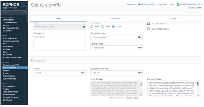
For ease of deployment, we’re building the tunnels on both peers at the same time. Therefore, we can copy/paste the configuration between each firewall and avoid any mistakes.
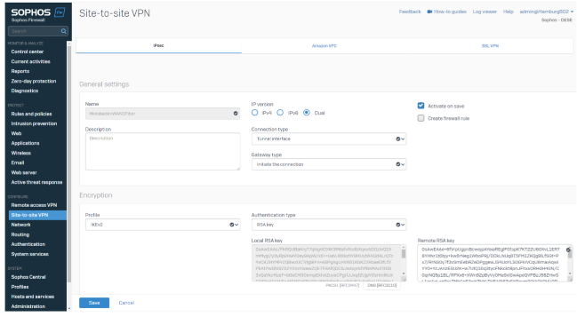
We’re using Route Based VPN Tunnel (XFRM or Tunnel Interface).
- Wiesbaden, as the HQ, is in respond-only mode.
- Profiles are predefined IKEv2 (internet Key Exchange Protocol Version 2) and can be selected on every SFOS installation.
- RSA Key as the tunnel defines Authentication Type, as RSA Key offers a quick configuration by copy/paste and does not require external key management.
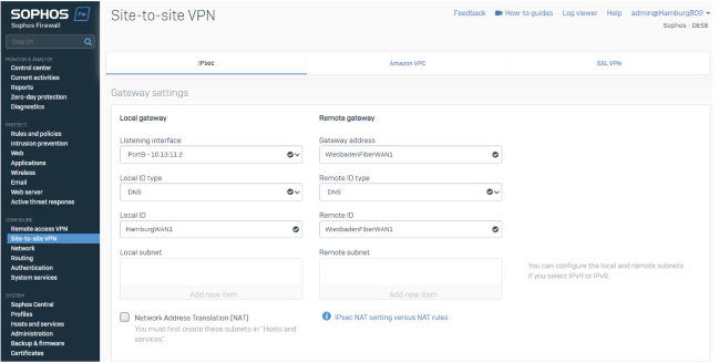
In Hamburg, we start the connection and select the same settings.
- RSA keys are defined by default for each appliance, and the remote key is expected from the peer appliance.
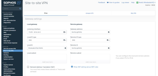
The last part combines the listing port on the local appliance and (remote) gateway address.
Listing Interfaces are WAN interfaces on the local firewall. We’ll select WAN1 (Fiber) for this tunnel. The gateway address reflects the WAN IP / FQDN of the remote location (WAN1 of Hamburg).
Note: We are using DNS hostnames for the remote peers. You’ll have different WAN IPs (Static IP or Dynamic DNS) based on your setup.
Best Practice: You can also use Dynamic DNS records for a Gateway address or a Wildcard (*) if you have a dynamic peer.
Additionally, we specify the Local ID Type DNS and give both proper names. This helps to identify the tunnels. This step isn’t mandatory but recommended.
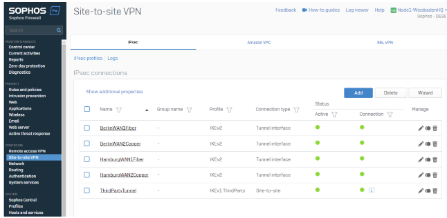
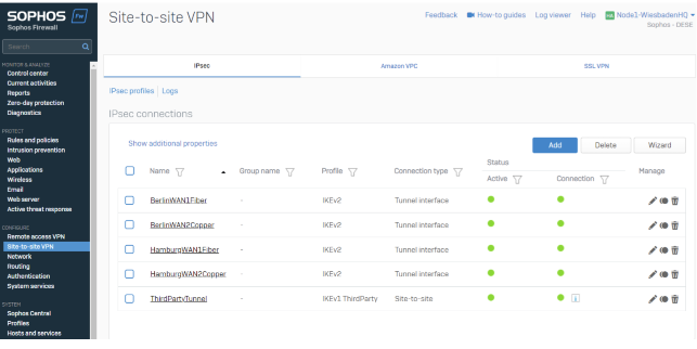
We'll be doing this four times for the 4 Tunnels at HQ and 2 in each location.
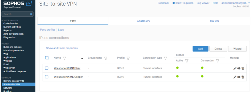
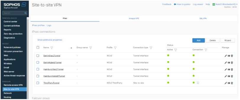
To verify this, we can check the tunnel status in the IPsec overview section by going to CONFIGURE>Site-to-site VPN>IPsec Tab.
HQ
Separate Site Location
XFRM Interface mapping recommendation
XFRM Interfaces are like long cables connecting two appliances, and both ends of the tunnel require an IP Address.
- It would be best if you did not reuse the same network range on multiple tunnels
- Segmentation is needed.
A common approach is to slice a /24 subnet into multiple /30 subnetworks like:
Tunnel1: 10.252.0.1/30 + 10.252.0.2/30Tunnel2: 10.252.0.5/30 + 10.252.0.6/30Tunnel3: 10.252.0.9/30 + 10.252.0.10/30 […] Tunnel64: 10.252.0.253/30 + 10.252.0.254/30
This approach does not require much planning, but it is difficult to identify the correct interface in case of an issue.
An alternative approach in this guide is to create readable segmentations per tunnel. We are assigning each tunnel a specific assignment.
XFRM Interface
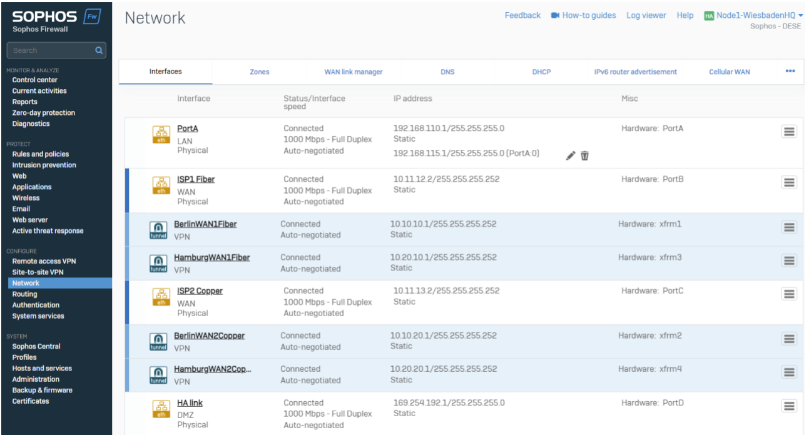
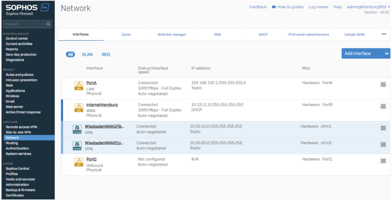
Route Based Tunnel (Tunnel Interface) creates an XFRM Tunnel interface. In Configuration >Network >Interfaces, you’ll see the XFRM Interface under each WAN Interface.
Note: You can click the blue line to expand the WAN Interface
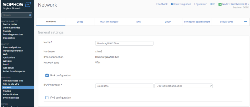
XFRM Interfaces are transfer networks. You need an IP Address on both ends of the tunnel, which must be in the same subnet range.
Best Practice: For better visibility, the XFRM Interface name can be matched to the tunnel name.
We strongly encourage you to set up an action plan for XFRM Interfaces.
There are multiple approaches to this setup, and our approach might be only an idea and not suitable for your setup. To avoid misconfiguration, you should lay out the XFRM Interface mapping before going into the configuration.
SD-WAN gateway
With the IPsec tunnels in place, we want to route traffic through those tunnels.
For routing, have multiple approaches, such as the following:
- Static Routing
- Dynamic Routing
- SD-WAN Routing.
We decided to use SD-WAN routes to build zero downtime and high utilization of all WAN interfaces.
The following setup will be needed
- Gateway
- SD-WAN Profiles
- SD-WAN Route
One gateway for every XFRM tunnel will be needed
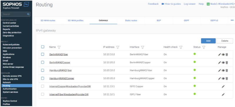
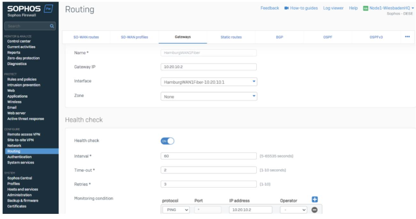
We chose the XFRM Interface and the peer gateway IP address.
In this case, the interface is 10.20.10.1, and the peer gateway IP address is 10.20.10.2.
- By selecting the Interface, it’s easy to identify the local IP address.
- Using a /30 XFRM assignment, we can identify the next IP address will be the gateway.
SD-WAN profiles
SD-WAN Profiles will be generated per location you want to make reachable.
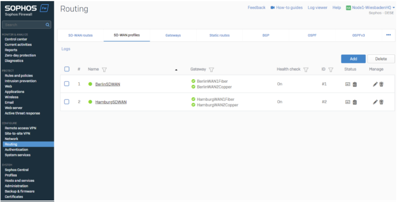
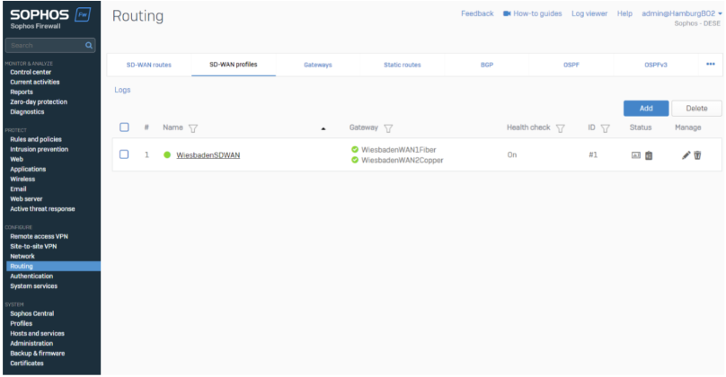
In the SD-WAN Profiles, we select all applicable locations and choose “Load Balancing”.
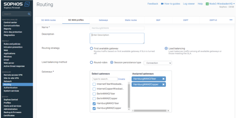
The load Balancing method decides whenever SFOS must select a specific VPN Tunnel.
You’ll find more information about Load Balancing in the Appendix.
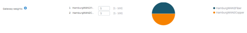
For our example, we use a gateway weight of 1 and 1, which results in 50% / 50% Load Balancing. Your setup may prioritize load balancing differently based on throughput or other criteria, like costs.
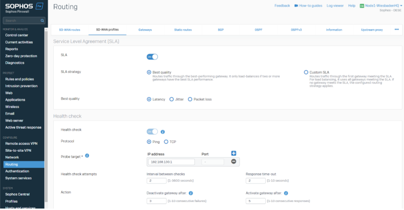
The SLA strategy can vary in your setup and be customized if needed. You can leave all settings per default or customize them based on your needs.
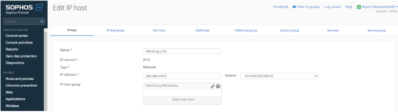
We are using the peer Location LAN IP as a probe target (192.168.130.1 is the Hamburg Site's LAN Port1).
SD-WAN Routes
Our last step is to make networks reachable. We use SD-WAN Routes to build up the routes between our locations.
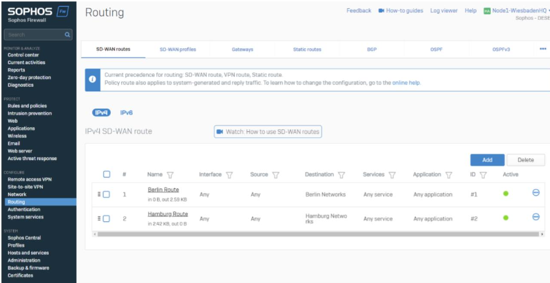
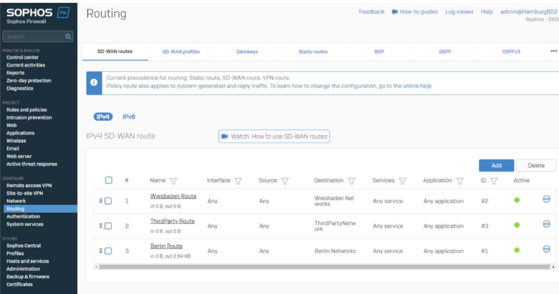
We created one SD-WAN Route per location so that it’ll be reachable
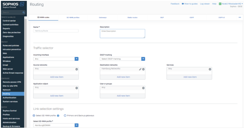
In the SD-WAN Routes, we are using IP Host Groups as a destination and leave the rest as ANY. You can customize this if you want to route only specifics.
Best Practice: By using IP Host Groups, we can always make sure all network ranges of all locations are routed correctly.
Best Practice: We are publishing and maintaining those objects via Sophos Central Firewall Management. Hamburg Networks, Berlin Networks and Wiesbaden Networks are automatically published on all Firewalls to ensure the routes are published. Changing the object in Central will change the routing as well.
You can use network objects as well; we found the usage of IP host groups more simplicist and less error sensitive.
Firewall Rules
We are using VPN to LAN and LAN to VPN Firewall rules in this Guide.
You should build your firewall rule concept based on your security need.
Redundancy and Zero Downtime
Proof of Concept
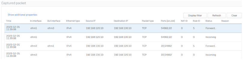
If a client from Berlin tries to reach a client in Hamburg, we can see the connection in the Diagnostic – Packet capture section.
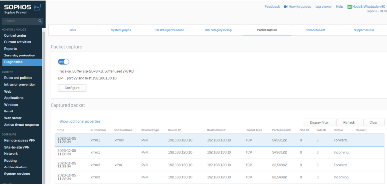
In Wiesbaden you’ll see packets coming from XFRM3, going out on XFRM1 and the response from XFRM1 going back to XFRM3.
Note: Packet capture shows the newest packet on the top – to read a connection you will start with the last session.
Failover scenario
Our WAN1 fails in Wiesbaden, which results in the failure of 2 / 4 tunnels. But still, everything is reachable through the other connection.
Zero Downtime failover
Our setup supports per default a zero-downtime failover in case of the failover scenario above. Our clients will not notice a failover to the other tunnel and all connections remain active.
We can see this in the packet capture as well.
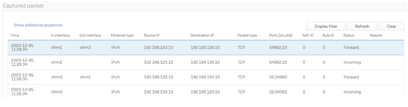
Before the failover we were using XFRM1 and XFRM3.
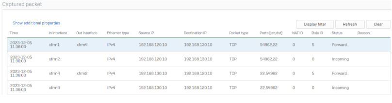
After the failover SFOS automatically switched to the XFRM4 and XFRM2 setup. Important to notice: The source ports of the connection are the same – The client is still connected to the server and did not stop (or rebuild) the connection.
Note: “IN Interface” in packet capture in case of a SD-WAN failover is reflected incorrectly in web admin. This is a known issue and only cosmetical.
SFOS will automatically fail back to the old VPN connection if the WAN1 comes back online. The source port is still unchanged.
Third-Party VPN
Connecting to a Third Party can vary based on the product used and the influence one has on the tunnel. Often a customer just gets a rule set of policies to use.
In our example, the Third Party requires us to NAT our network within the Tunnel (masquerade), and it offers a network range we want to reach. Additionally, we get a rule set of IPsec requirements to follow. This section is also in the Appendix.
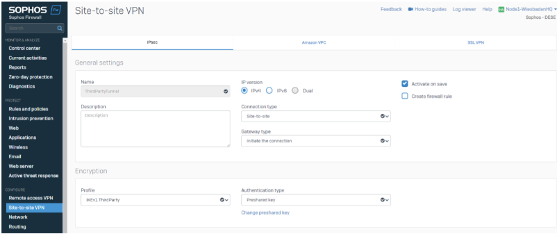
We’re building up the Tunnel with Site-to-Site Type (policy-based) and initiating the connection.
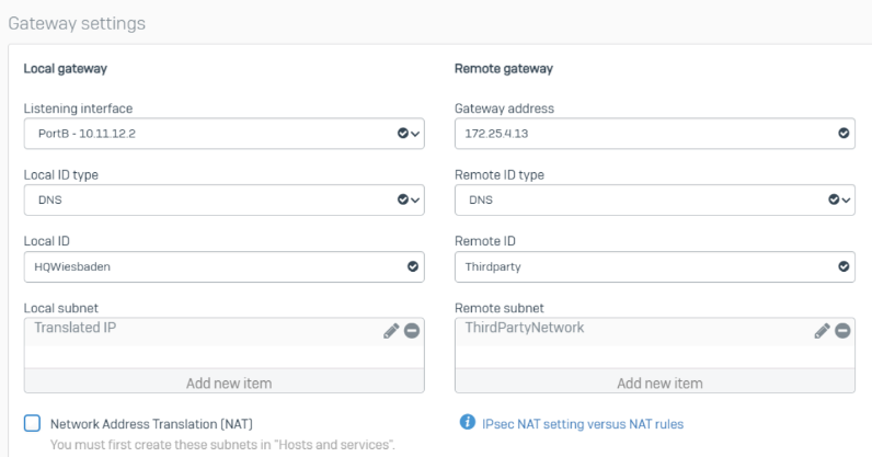
In the Gateway Settings, we must specify the local and remote subnets.
Based on the requirements, we use “ThirdPartyNetwork” as stated by the ThirdParty and use the required Translated IP in the Local Subnet. To reduce the complexity of this guide, we aren’t giving examples of those IPs.
We need to create a NAT Rule as well.
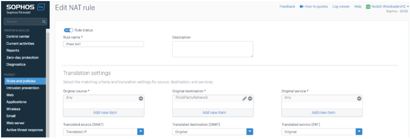
The NAT will translate every traffic going to the third-party network and MASQ the traffic to the Translated IP.
As the last step, we must generate an IPsec Route on the CLI for this destination network.
The command be: system ipsec_route add net <remote subnet> tunnelname <ipsec_tunnel>
system ipsec_route add net 192.168.3.0/255.255.255.0 tunnelname ThirdPartyTunnel
Note: You can use “TAB” for auto-complete
The ThirdPartyRessource is now reachable in Wiesbaden. We need an additional SD-WAN Route to make it reachable in Berlin/Hamburg.
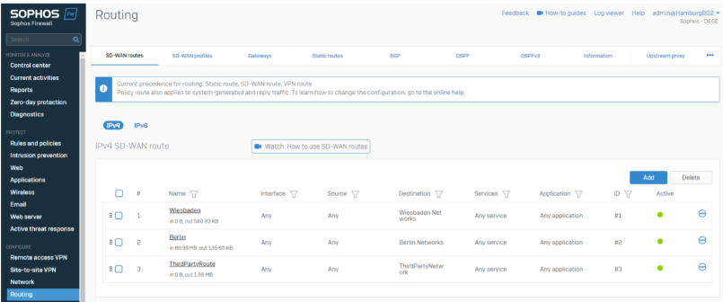
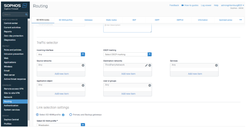
This SD-WAN Route will route the traffic going to the ThirdPartyNetwork through Wiesbaden to the ThirdParty.
Scalability
Our guide reflects a smaller setup with two remote locations, and we want to review the options to scale this system to larger networks.
Steps to attach a new location
Creating a new location includes the following configuration steps:
- IPsec Tunnel on both Appliances
- IPsec XFRM Interfaces on both Appliances
- Gateways on both Appliances
- SD-WAN Profile on both Appliances
- SD-WAN Routes on both Appliances
Using SD-WAN Orchestration in Sophos Central
Sophos Central supports the SD-WAN Orchestration with the xStream Protection License and generates all points above for all managed appliances.
You'll find more information here: Sophos Firewall: Managing Firewall and SD-WAN Orchestration.
Dynamic Routing
Administrators might want to use dynamic routing instead of SD-WAN routes for larger network deployments. SD-WAN routes offer an easy way to deploy latency, jitter, and packet loss measurement and routing decisions without the need to be experienced with the routing protocol itself. You may find more information about dynamic routing in the appendix.
Appendix
- WAN Link Load Balancing
- SD-WAN Profiles
- NAT in Policy Based
- Dynamic Routing( OSPF)
- Dynamic Routing (BGP)
Revamped RR
[edited by: Erick Jan at 9:35 AM (GMT -7) on 18 Sep 2024]


