Instructions here are for download and install of the OVA on MS Hyper-V for an NDR Sensor. The same install process can be followed when installing the Data Collector for Log Collectors without an NDR Sensor.
Step 1 - Download OVA
Select the Action 'Download OVA' the zip file will be placed in your downloads folder
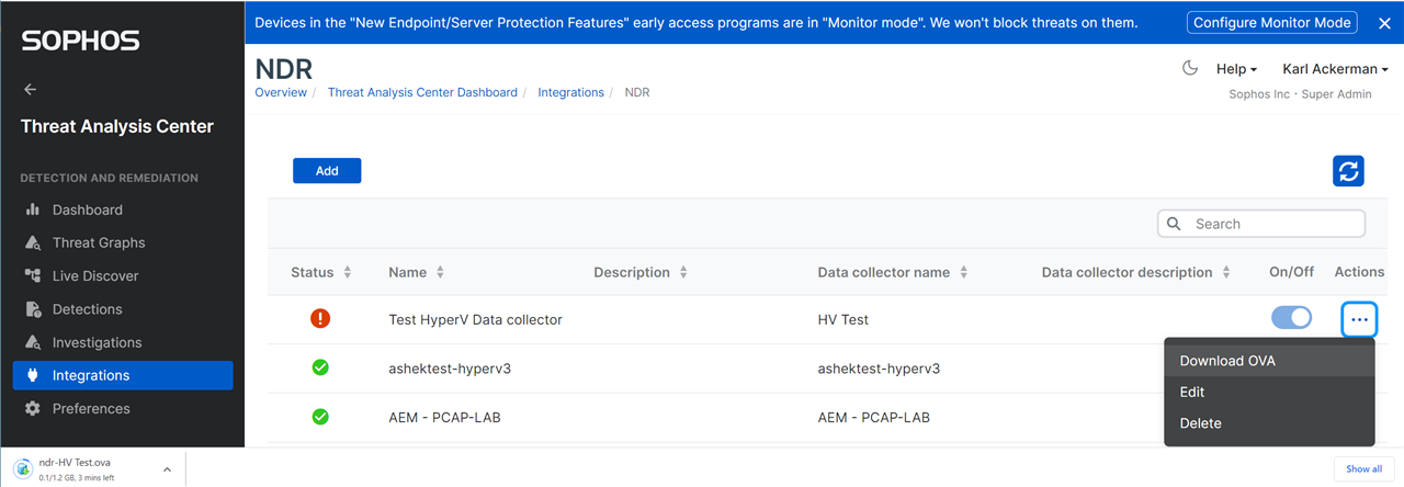
The zip file that contains the virtual drives, seed.iso, and a PowerShell script to make the import process as easy as possible.
CAUTION: One thing to note that is different between VMware ESXi and Hyper-V support is that the NDR application is not able to support jumbo network packets. This is due to a limitation in the driver used by Hyper-V to capture packets.
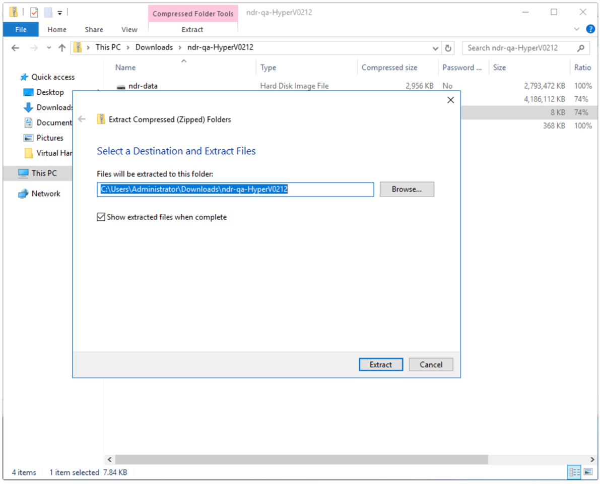
STEP 2 : Extract the zip file to a folder on your hard drive
You will need to have either downloaded the ZIP to the server that will host the Hyper-V virtual appliance or copy the ZIP or its contents to that server.
STEP 3: Execute the Powershell
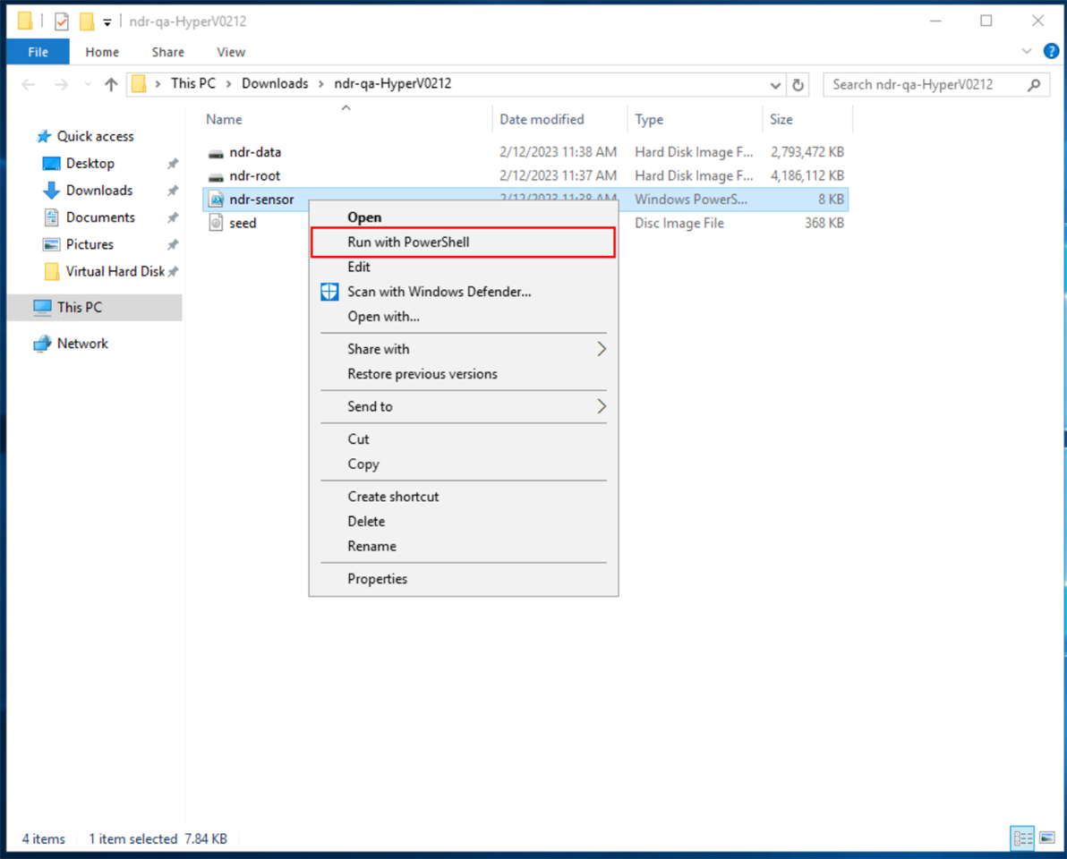
Once you have extracted the zip file, navigate to the folder where you extracted the items to and right click on the ndr-sensor.ps1 file. Then select 'Run with PowerShell'.
You will most likely need to allow the file to be run, if this is the case then click the Open button in the Security Warning popup dialog box.
STEP 4: Answer the PowerShell execution prompts
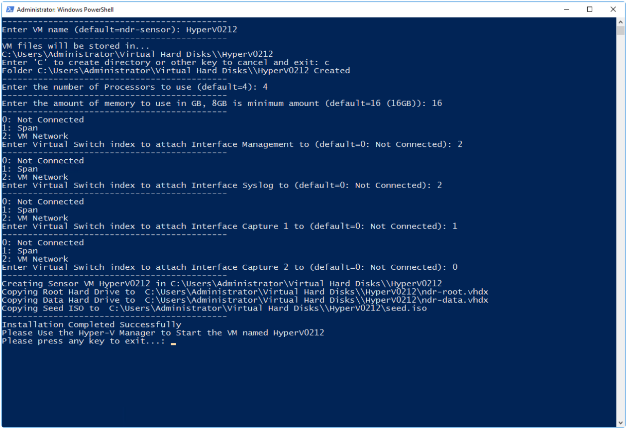
The script will ask a serious of questions that will help automate the import process and setup the vSwitch you select for the capture interfaces to read your mirrored traffic.
-
You will be asked to give the virtual machine a name
-
The PowerShell script will detect your default install location for virtual drives, and ask to create a new folder in that location.
-
You will be asked to specify how many processors the VM should have. (Default 4)
-
You will be asked to specify how much RAM the VM should be allocated (
-
You will be asked which vSwitch should be attached to the management interface and shown a list of your current vSwitches. The first entry in the list will be selected as the default.
-
You will be asked which vSwitch should be attached to the syslog interface and shown a list of your current vSwitches. The first entry in the list will be selected as the default.
-
You will be asked which vSwitch should be attached to the SPAN1 interface and shown a list of your current vSwitches. The first entry in the list will be selected as the default. If this is a “log collector only” VM, then you can use whatever vSwitch you want as a placeholder and disconnect this interface in the VM settings after it has been imported.
-
You will be asked which vSwitch should be attached to the SPAN2 interface and shown a list of your current vSwitches. The first entry in the list will be selected as the default. The second span port is not needed for all NDR deployments. It is only needed when the customer has two sources for SPAN traffic that need to be monitored. An example of this would be a physical switch, and a vSwitch in Hyper-V that is hiding traffic from the physical switch. If this is a “log collector only” VM, then you can use whatever vSwitch you want as a placeholder and disconnect this interface in the VM settings after it has been imported.
After you have answered all of the questions, the PowerShell script will then copy the VM files to the new folder in your default virtual drive location and setup the VM in Hyper-V. Once this process is finished you will see an “Installation Completed Successfully” message, and you can press any key to exit the script.
STEP 5: Review settings in Hyper-V manager
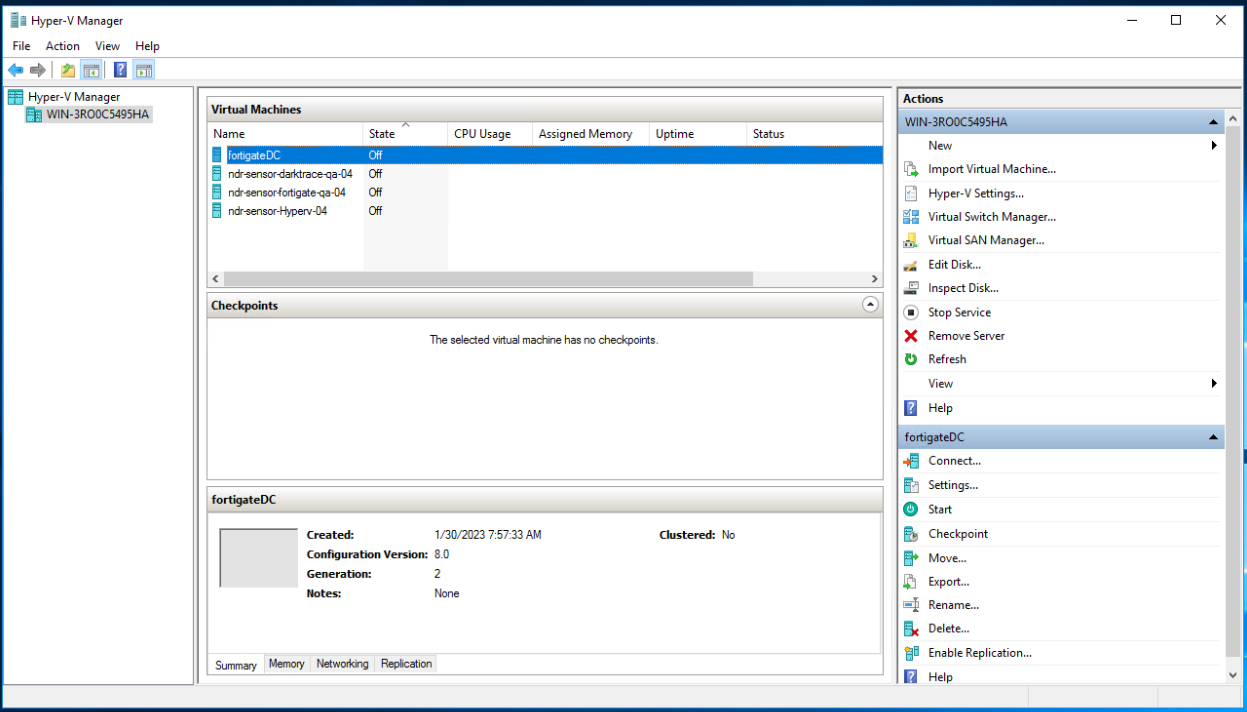
After the script is finished running, you can open the Hyper-V Manager (if it isn’t already open) and you should see the VM added to the list of virtual machines. If you need to change any settings (or confirm the ones you selected in the PowerShell script), you can do so at this point in time.
STEP 6: First Boot process
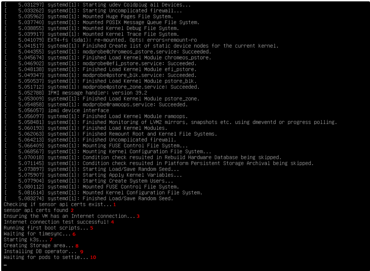
After a data collector has been imported and powered on for the first time, it will go through a first boot process and then reboot once it’s finished. This process is necessary to ensure some pieces of our software are properly installed and each VM has unique certificates for things like SSH and our Sensor API application.
A series of setup activities will be performed
-
Checks if the necessary SSL certificates for sensor api exist
-
Reports if they are found, and if not then it will generate them
-
Ensure the VM has a Internet connection by going to https://central.sophos.com
-
Reports if the connection test was successful
-
Begins running the first boot scripts
-
Waits for the NTP client to sync the VM’s time with ntp.ubuntu.com. This is necessary to generate K3s SSL certificates with a valid timestamp
-
Starts K3s, a light weight Kubernetes application
-
Sets up the Clickhouse DB storage area on disk
-
Installs the Clickhouse DB operator in K3s
-
Waits for all K3s pod operations to finish
After this process has finished, the virtual machine will reboot.
Trouble shooting:
VM has no Internet connection:

If you receive the message “VM has no Internet connection” during the first boot process then this means that the VM attempted a HTTP GET request for https://central.sophos.com, but was unsuccessful. If this is the case, then you will taken to a Console UI screen allowing you to alter their network configuration settings for the management port.

While you can update the network settings on this screen if needed, it is recommended that you check these three things first.
-
Check if you assigned the correct vSwitch (Hyper-V) to the MGMT interface while setting up the VM?
-
Is the vSwitch (Hyper-V) behind a firewall that isn’t allowing the VM to Sophos Central, or any of the other URL’s and protocols listed in below:
- archive.ubuntu.com
- ntp.ubuntu.com
- security.ubuntu.com
- changelogs.ubuntu.com
- api.snapcraft.io
- baltocdn.com
- sophossecops.jfrog.io
- *.sophos.com
- jfrog-prod-*-main.s3.amazonaws.com
- raw.githubusercontent.com
- auth.docker.io
- registry-1.docker.io
- tf-nta-sva-images-cloudstation-eu-west-1-prod-bucket.s3.eu-west-1.amazonaws.com
- tf-nta-sva-images-cloudstation-eu-central-1-prod-bucket.s3.eu-central-1.amazonaws.com
- tf-nta-sva-images-cloudstation-us-east-2-prod-bucket.s3.us-east-2.amazonaws.com
- tf-nta-sva-images-cloudstation-us-west-2-prod-bucket.s3.us-west-2.amazonaws.com
- tf-nta-sva-images-cloudstation-ca-central-1-prod-bucket.s3.ca-central-1.amazonaws.com
- tf-nta-sva-images-cloudstation-ap-southeast-2-prod-bucket.s3.ap-southeast-2.amazonaws.com
- tf-nta-sva-images-cloudstation-ap-northeast-1-prod-bucket.s3.ap-northeast-1.amazonaws.com
- tf-nta-sva-images-cloudstation-ap-south-1-prod-bucket.s3.ap-south-1.amazonaws.com
- tf-nta-sva-images-cloudstation-sa-east-1-prod-bucket.s3.sa-east-1.amazonaws.com -
Is the IP address assigned to the VM, whether static or dynamic, part of the network assigned to the vSwitch (Hyper-V) that was assigned to the MGMT interface while setting up the VM?
