

Disclaimer: This information is provided as-is for the benefit of the Community. Please contact Sophos Professional Services if you require assistance with your specific environment.
______________________________________________________________________________________________________________________________________
Table of Contents:
- Deployment Order
- Network VLAN & Subnet Details:
- Configuration
- Step 1 - Configure the Sophos Firewall*Firewall has already completed Initial Setup - Base Configuration in place*
- Step 2 - Configure the Sophos Switch via Central*unless stated otherwise, all configuration is done from Sophos Central*
- Step 3 - Connecting the Hardware
- Step 4 - Configure Sophos Central Wireless: SSIDs and Sophos Access Points
- Step 5 - Important Items to Test/Finalize Setup
- Step 6 - Turn up and Verify Connectivity
Deployment Order
- Sophos Firewall (XGS126)
- Sophos Switch (CS110-24FP)
- Sophos Wireless (AP6-420)
Network VLAN & Subnet Details:
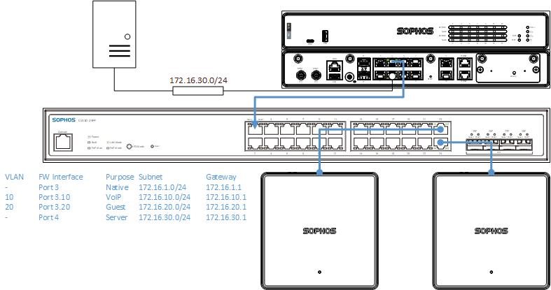
| VLAN | FW Interface | Purpose | Subnet | Gateway | DNS | DNS2 | DHCP Start | DHCP End |
| - | Port 3 | Native | 172.16.1.0/24 | 172.16.1.1 | .100 | .200 | ||
| 10 | Port 3.10 | VoIP | 172.16.10.0/24 | 172.16.10.1 | .100 | .200 | ||
| 20 | Port 3.20 | Guest | 172.16.20.0/24 | 172.16.20.1 | .100 | .200 | ||
| - | Port 4 | Servers | 172.16.30.0/24 | 172.16.30.1 | .100 | .200 |
Configuration
Step 1 - Configure the Sophos Firewall
*Firewall has already completed Initial Setup - Base Configuration in place*
- Learn more about Interfaces in Sophos Firewall:
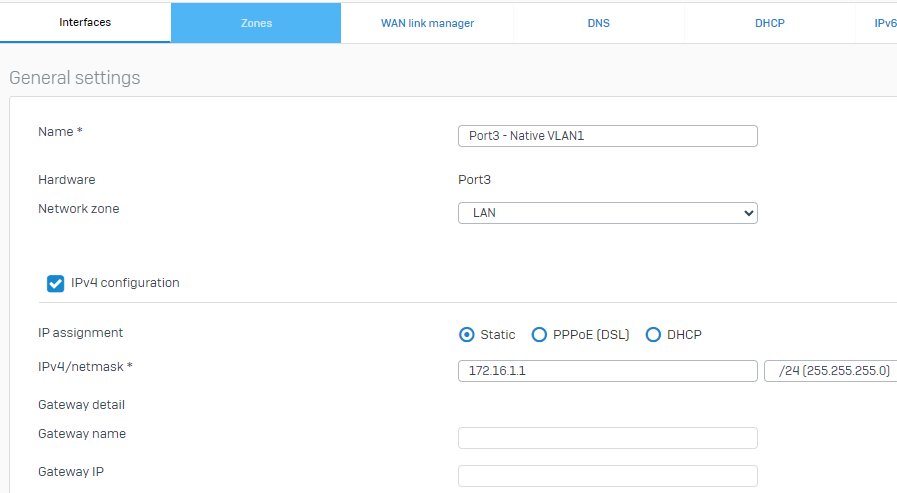
1.1 - To begin, we configure Port3 on the Firewall. As we do, there is no need to specify it as VLAN1 since the packets on that interface will reach the switch, which has a default PVID of VLAN1, so untagged packets from this interface will default to VLAN1 on the connected switch port and egress from the switch will also be untagged:
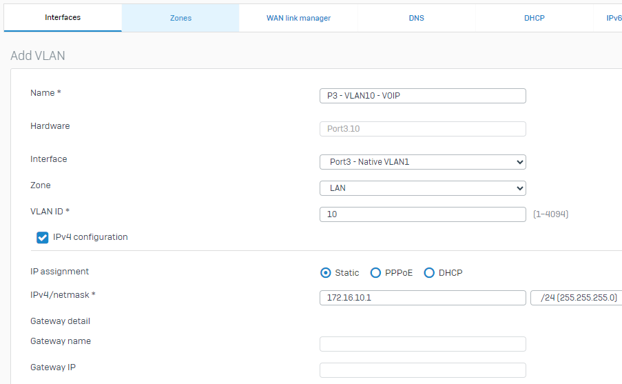
1.2 - Next, we will configure VLAN10 as a sub-interface on Port3. From Network > Interfaces > Select "Add Interface" > "Add VLAN". This will create a sub-interface of Port3.10 as follows:
- Learn More about VLANs for Sophos Firewall:
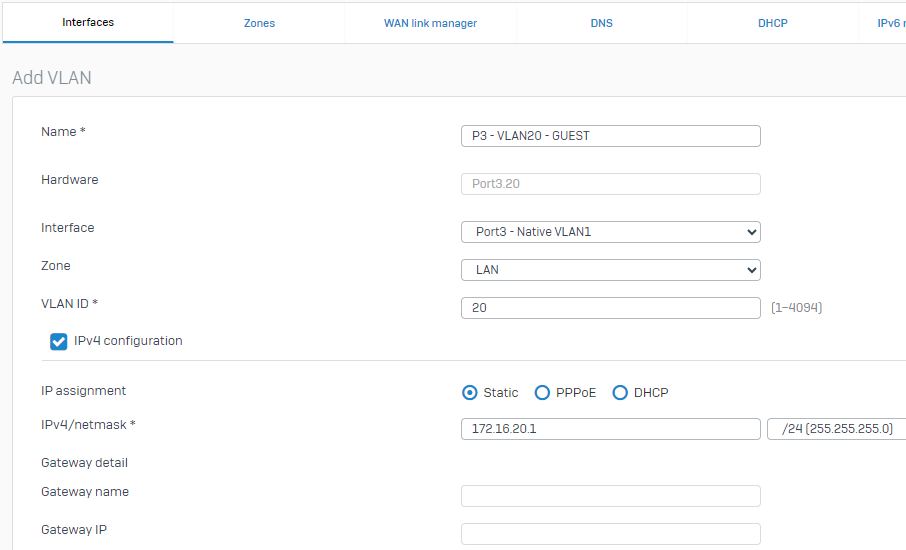
1.3 - Next, we will configure VLAN20(GUEST) as another sub-interface on Port3. From Network > Interfaces > Select "Add interface" > "Add VLAN". This will create a sub-interface of Port3.20 as follows:
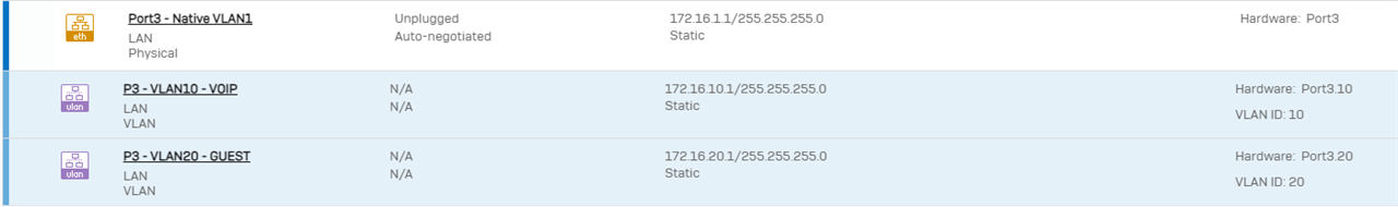
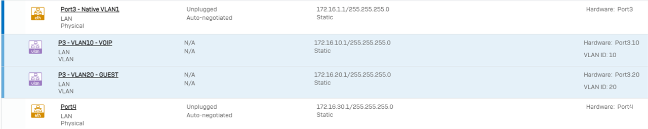
1.4 - Before proceeding, let's confirm our Port3 interfaces are configured correctly. In order to see all sub-interfaces, expand the blue bar to the left of the interface when viewing Network > Interfaces:
1.5 - Next, we will configure Port4 on our XGS126 as the "Servers" interface, i have not modified the interface name to reflect Servers in the image below, but you certainly can describe the interface here, for example, as Port 4 - Servers:
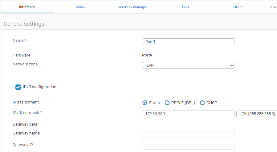
1.6 Before proceeding, verify your configuration on Port4:
Step 2 - Configure the Sophos Switch via Central
*unless stated otherwise, all configuration is done from Sophos Central*
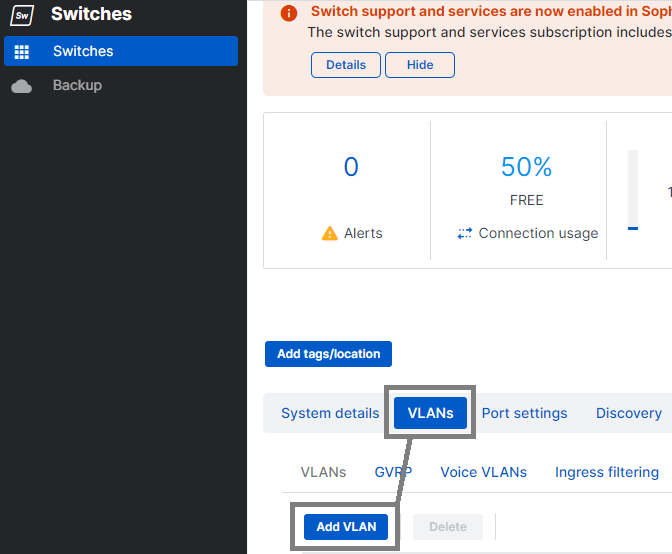
2.1 - In order to ensure the switch is aware of our VLANs, we want to add VLAN10[VoIP] and VLAN20[GUEST] to the Sophos CS110-24FP Switch. Log in to Sophos Central, browse to the switch you wish to configure, then select VLANs > Add VLAN
2.2 - Name the VLAN "VoIP for VLAN10 and "GUEST" for VLAN20. You will notice that you must also tag the appropriate interfaces so that the switch will recognize the VLAN tagging on packets and handle them appropriately. (In this example, just tag all interfaces, unless of course, you already have custom configurations, in which case tag appropriate to your deployment)
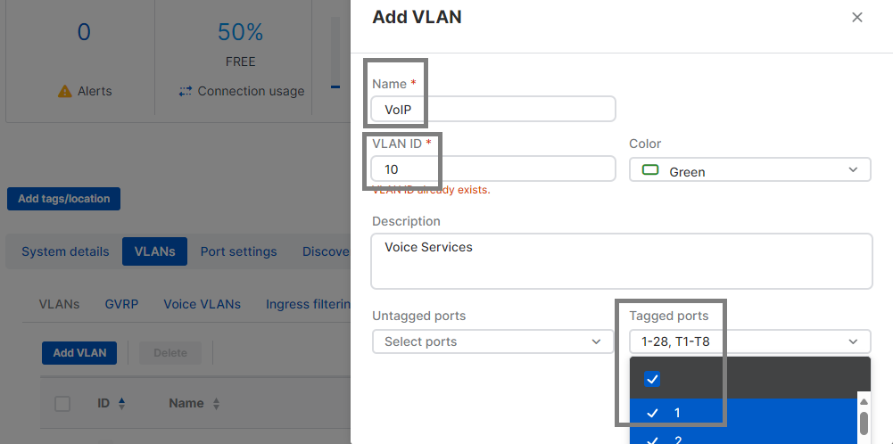
2.3 - After successfully adding VLAN10, repeat the same process to add VLAN20, of course, changing the VLAN ID you see in the image above to 20
2.4 - Verify that the tasks are completed successfully. For a brief moment the sync issues indicator may go red, but will update once tasks are complete.
Step 3 - Connecting the Hardware
3.1 - Connect a network cable between Port3 and any available interface on the Sophos Switch. If you were uplinking to the Sophos Firewall over fiber, both units would require SFP modules and fiber optic patch cables
3.2 - Connect a network cable between Port4 and the Server network
Step 4 - Configure Sophos Central Wireless: SSIDs and Sophos Access Points
All Sophos APs are AP6-420 units and support 2.4 and 5 GHz frequencies.
4.1 - AP6-420 is connected to Ge0/24 on the Sophos Switch
4.2 - AP6-420 No.2 is connected to Ge0/23 on the Sophos Switch.
4.3 - The AP6 Access Points are registered in Sophos Central successfully after entering their serial numbers before timeouts.
- Learn more about registering Access Points in Sophos Central
4.4 - From within Sophos Central, looking at the Access Point under "Settings", we’ll set our Management VLAN ID = 1 and LAN1 Tagging = Untagged
- Learn more about VLAN Configuthe n for AP6 Access Points
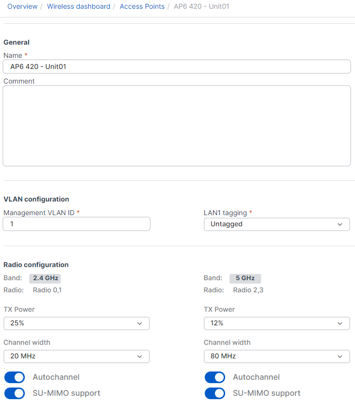
4.5 - With AP6-420 Unit 01 now in Central, we can add other access points to the network in the same way and same configuration for Management VLAN ID and LAN1 Tagging.
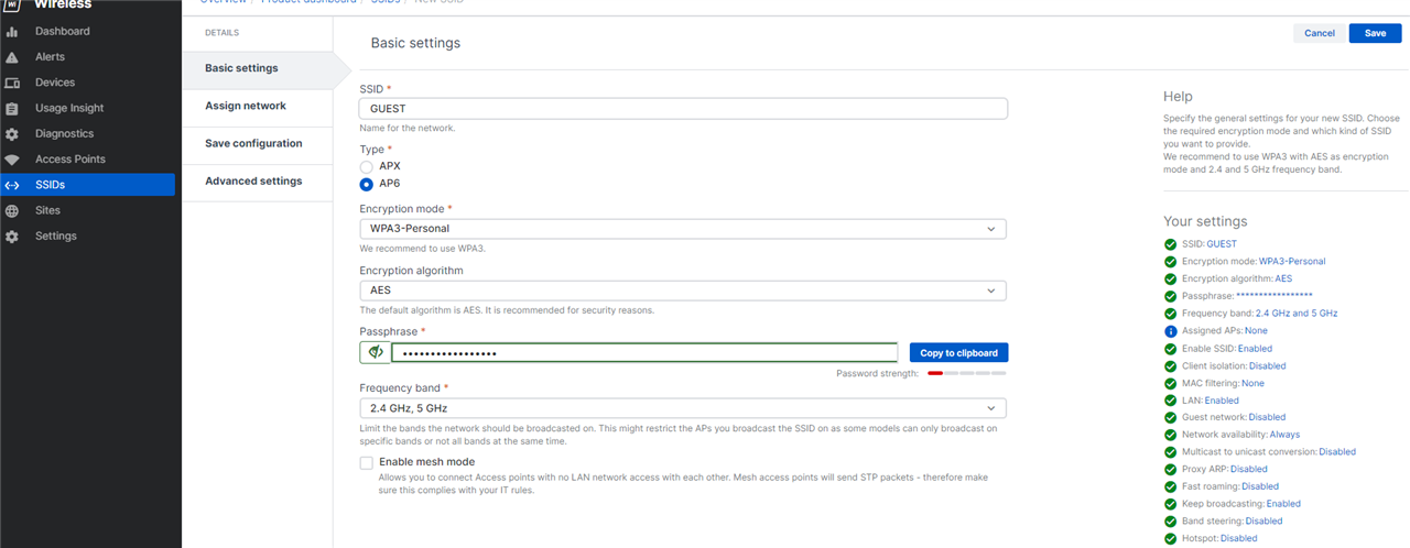
4.6 - We’ll build our SSIDs and associate them with the correct VLANs. As our VoIP Network won’t utilize Wireless, we only need to worry about the GUEST VLAN20 and VLAN1. From My Products > Wireless > SSIDs, you want to select "Create" to add a new SSID.
4.7 - For GUEST, configure as follows:
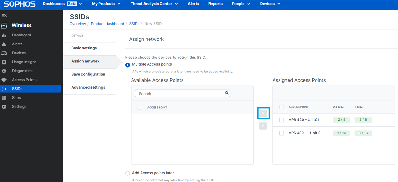
4.7.1 - In Assign Network, assign this SSID to "Multiple Access Points" and select the AP6-420 Units we have registered.
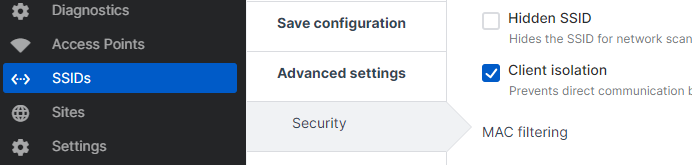
4.7.2 - Do not "Save Configuration" just yet, instead select "Advanced Settings" > "Security" > Place a checkbox in "Client Isolation"
- Learn more about Client Isolation:
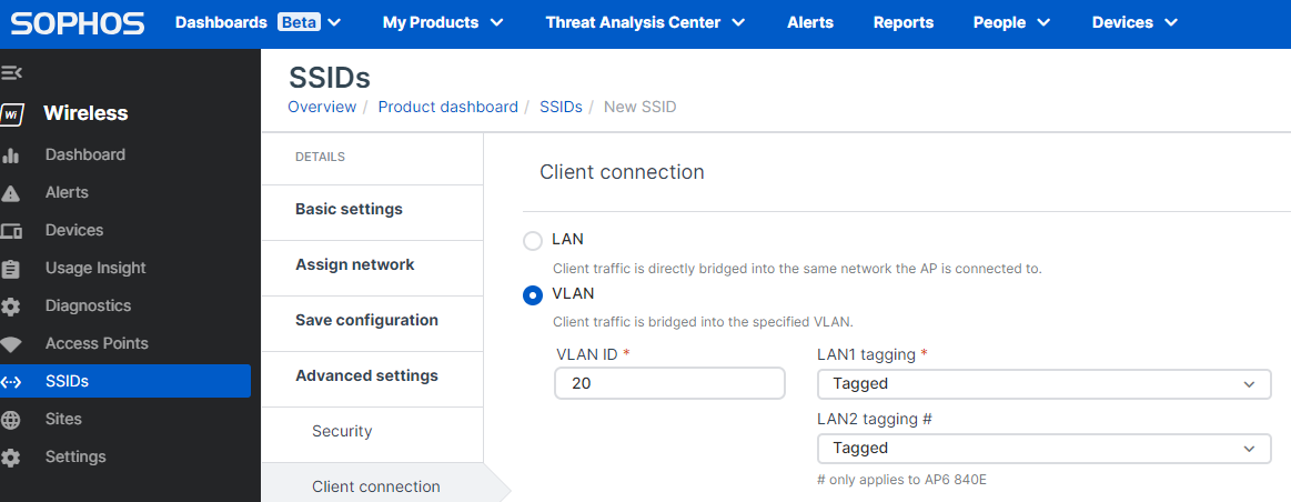
4.7.3 - Select "Client Connection" next and select the radio button "VLAN" and change your VLAN ID from 1 to 20, set LAN1/LAN2 Tagging = Tagged
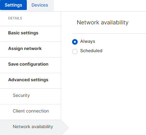
4.7.4 - In Network Availability, determine the schedule or select "Always Available"
4.7.5 - In Quality of Service, select the additional options you would like to implement for this SSID
- Learn More about the Quality of Service Options
4.7.6 - In Captive Portal, you can enable this if you would like to configure Captive Portal / Hotspot settings for your guest wireless network.
- Learn More about the Captive Portal
4.8 - For your VLAN1 SSID, we’ll carry out the same steps above, except on the Client Connection settings, we’ll leave the radio button for "LAN" selected, no VLAN information is required in this specific setup for VLAN1.
Step 5 - Important Items to Test/Finalize Setup
5.1 - Ensure a DHCP Scope is configured for each subnet, including, VLAN10 and VLAN20. For the server subnet on Port4, you may be assigning addresses statically or via DHCP. If via DHCP, then a scope should be configured for that subnet as well, and all of them activated. If any specific DHCP Options are required, enter those in the appropriate DHCP Scope on the Sophos Firewall or your preferred DHCP Server.
5.2 - Ensure that your DHCP Scope specifies the Sophos Firewall as its DNS Server as follows:
- VLAN1 DNS should be configured in the DHCP Scope = 172.16.1.1
- VLAN10 DNS should be configured in the DHCP Scope = 172.16.10.1
- VLAN20 DNS should be configured in the DHCP Scope = 172.16.20.1
Note: If your Servers will be handling DNS, have the scope assign the IP address for the internal DNS servers, then use the Forward Lookup options to either resolve to the Sophos Firewall or your Sophos Central DNS Protection IP addresses (if licensed with XStream)
5.3 - Ensure you accommodategured LAN-to-LAN Zone Firewall Rules and Security Policies between Port3 and Port4.
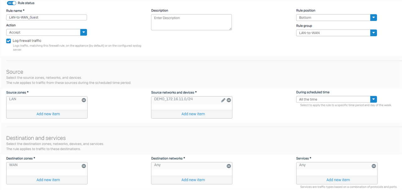
5.4 - Ensure you have configured LAN-to-WAN Zone Firewall Rule and Security Policies to accomodate Outbound access for ALL subnets, including the GUEST network. I recommend the use of Rule Groups capturing the Zone-to-Zone overview, then creating individualized rules based on the subnets and services needs. For your Guest network, create a rule such as:
- SrcZone: LAN SrcNet: VL20_GuestNet Services: Any (or HTTPS/HTTP/DNS) DstZone:WAN DstNet: Any
5.5 - Ensure you have configured NAT correctly, or utilized the Default SNAT and removed all "LinkedNAT".

Step 6 - Turn up and Verify Connectivity
6.1 With everything now configured, active, and connected, you’ll have:
- a functioning main LAN
- a VoIP LAN
- a separate GUEST LAN
- On-prem segmentation in place
- the ability to fully configure subnets can communicate other via Firewall rules
- the ability to apply LAN-to-LAN IPS and security controls.
- on-prem servers are isolated from any risks inherent to being in the same subnet.
You absolutely could implement another VLAN on this switch and run Server traffic from Port4 through, for example, VLAN30 with a subnet of 172.16.30.0/24. There are a few alternatives to this configuration that all work quite well. The XGS126 has sufficient physical ports that we could physically assign each subnet to a physical interface rather than just Port3 in this example, if you would like to see that as a guide, please reply and let me know.
6.2 Connect to your GUEST SSID and verify you can only communicate with the Internet, but cannot talk to any local devices on the GUEST or other subnets.
6.3 Connect to your main LAN and verify you can communicate with the Internet, the Server subnet, and VoIP subnets.
6.4 Verify that no communication is permitted between GUEST and any other subnet (i.e, Servers, VLAN1, VoIP)
______________________________________________________________________________________________________________________________________
Disclaimer, Grammar, Horizontal lines, Table of Contents, Formatting, TAGs
[edited by: Raphael Alganes at 3:13 PM (GMT -7) on 17 Apr 2024]