Important note about SSL VPN compatibility for 20.0 MR1 with EoL SFOS versions and UTM9 OS. Learn more in the release notes.
Important note about SSL VPN compatibility for 20.0 MR1 with EoL SFOS versions and UTM9 OS. Learn more in the release notes.


Disclaimer: This information is provided as-is for the benefit of the Community. Please contact Sophos Professional Services if you require assistance with your specific environment.
In this recommended read, we'll discuss deploying the Sophos firewall in Fault Tolerance, a.k.a. AA (Active-Active) mode on the AWS platform. We will use the Amazon transit gateway (TGW) feature to support the hub-and-spoke model for this deployment.
The transit gateway facilitates node redundancy for the Sophos Firewalls, and BGP communicates routing information with the rest of the AWS infrastructure in the customer account.
If you’re interested and want to know more about this technology, check out Amazon's documentation on Transit gateway: https://aws.amazon.com/transit-gateway/
Sophos Firewall is available from the AWS marketplace for both High Availability and Fault Tolerance deployment methods; however, in this document, we will focus on the Fault Tolerance (AA) deployment method.
Deploying the Sophos Firewall nodes in a separate VPC for traffic management and routing purposes is recommended.
While deploying the firewalls into the same VPC as other backend workloads is possible, different instructions will be required for the TGW attachment and route table creation. So feel free to contact your Sophos account representative if your setup requires a single VPC deployment.
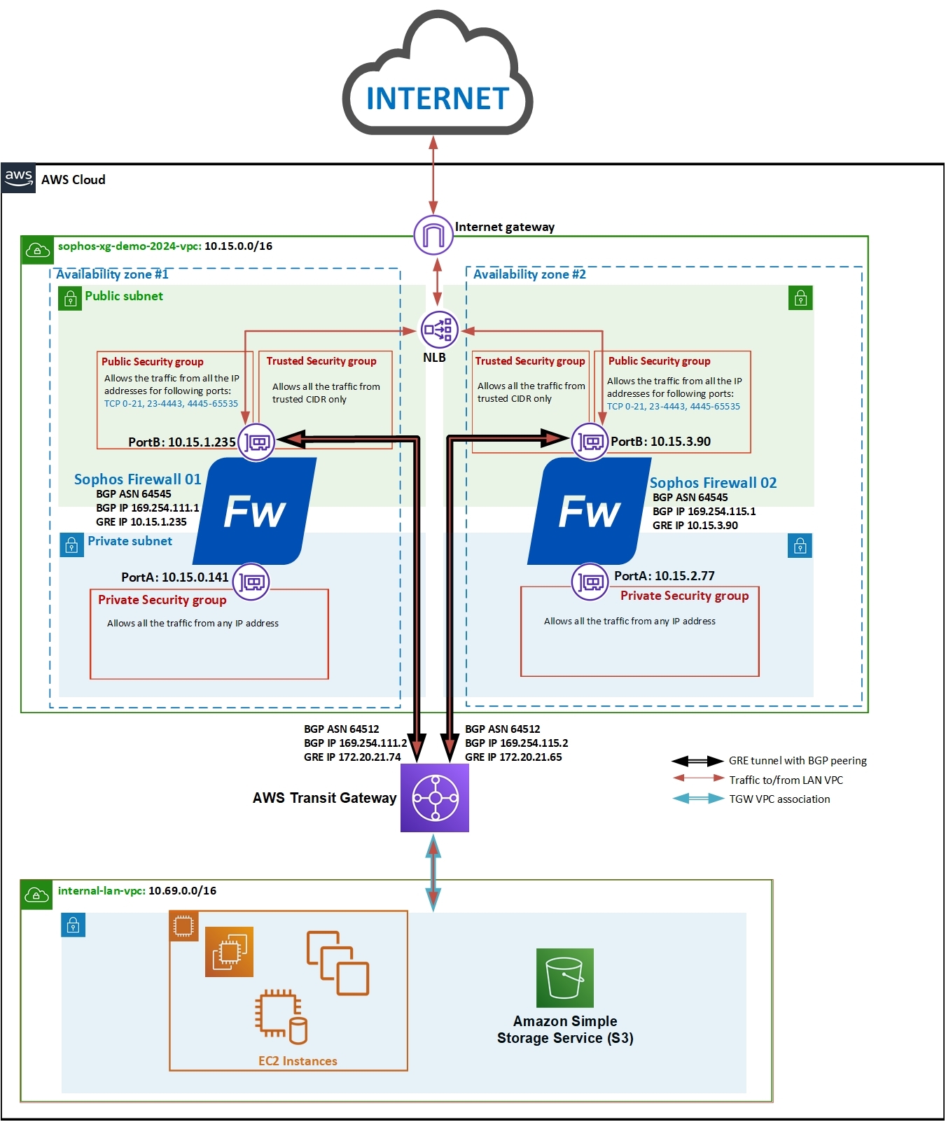
Here is the network diagram that we’re considering for this deployment. Both the Sophos firewall instances will be deployed in a separate VPC, connecting with the LAN network VPC via the transit gateway.
Note: The IP addresses used in this setup and document are for demo purposes. You can always use other IP addresses in your deployment scenario.
1. (Optional if you already have a key pair created in your account.) Once logged into your AWS web console, click Services > EC2 and scroll down to click Key Pairs.
Click the Create Key pair button, enter an appropriate name, select ppk, and finally, click the Create Key pair button to automatically download the private key to your computer. You can later use it to access the Sophos firewall instance via SSH.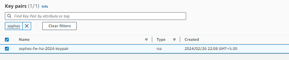
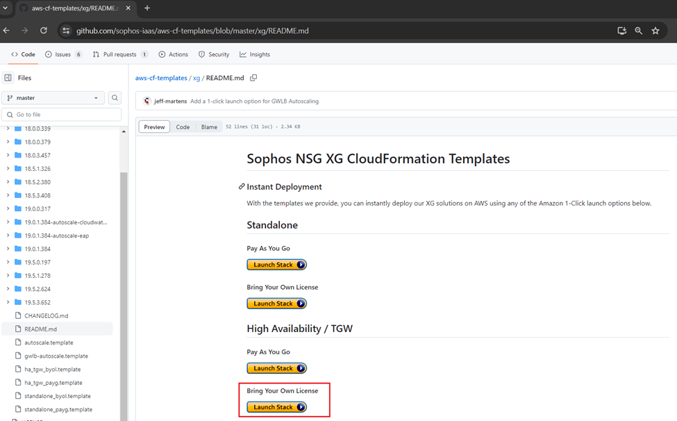
2. Access the GitHub repository using the link below:
https://github.com/sophos-iaas/aws-cf-templates/blob/master/xg/README.md
3. Under the High Availability / TGW section, you can see two deployment options available:
Pay As You Go (PAYG) and Bring Your Own License (BYOL).
For this document, we’re considering the BYOL option, so click the Launch Stack button.
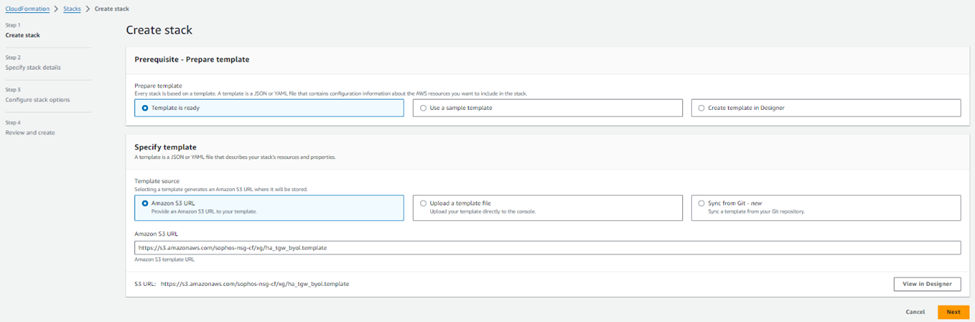
4. This will open your AWS web console and redirect to the CloudFormation stack page with an S3 URL referring to the HA deployment template. Click the Next Button
5. Enter an appropriate stack name, keep the AMI ID as autodetect, and select the required instance size from the drop-down list.
Select Availability zones for each firewall node and ensure both have different AZs selected to achieve High Availability.
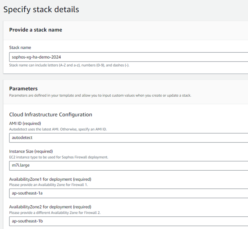
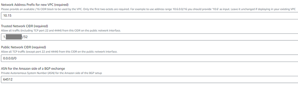
6. Configure the network address for the new VPC. You need to enter the first two octets of the network IP. In this deployment, we’ll use the default network address 10.15.
Enter the administrator's public IP address when deploying this firewall in the trusted network CIDR. This IP address will have full management access (SSH and web Console) to the Sophos Firewall units.
Enter the Public Network as 0.0.0.0/0, or you can enter a specific IP address with access to all the ports from outside except the management ports 22 and 4444. Enter a desired BGP ASN to represent the Amazon Transit Gateway in communication with the firewall (the default value is 64512; it doesn't need to be changed unless this ASN is already used somewhere in your BGP setup).
7. Enter the serial numbers of your registered licenses in the ‘Sophos Firewall Serial Numbers’ field in a comma-separated format (for example, 123456789,23467890).
Enter the following details:
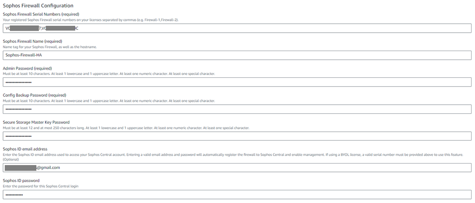
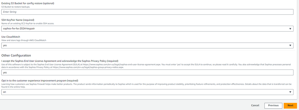
8. The S3 bucket name is an optional field that can be used for the backup-restore process. You can leave this field blank.
Then select the SSH keypair that was created previously in step #1.
The logs of Sophos Firewall EC2 instances can be stored in CloudWatch. To enable this functionality, select yes from the drop-down list.
Enter "yes" in the End User License Agreement field after reading and agreeing to the terms and conditions of Sophos EULA and privacy policy.
Now, if you wish to participate in the customer experience improvement program, you can select the "on" option from the drop-down menu or the "off" option. We’ll select On and click Next.
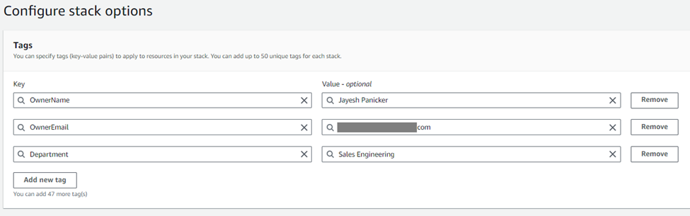
9. Optionally, you can add Tags for this deployment or leave the fields as-is.
For the demonstration purpose, we’ll add the OwnerName, OwnerEmail, and Department tags for this CloudFormation stack deployment and click Next.
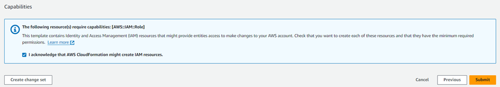
10. Read through the deployment configuration summary, then turn on the checkboxes for allowing IAM resources creation permission, and finally click the Submit button
11. It will show the progress of the stack deployment for both the firewall instances and the associated resources. After 15-20 minutes, it’ll show the status as Create Complete, meaning that both the firewall instances have been deployed successfully.

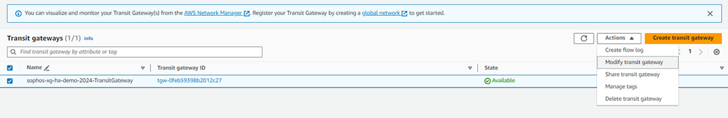
1. Navigate to Services > VPC, scroll down to the Transit Gateways section, and click Transit Gateways. Select the transit gateway configured by the CloudFormation stack, and from the Actions section, click Modify.
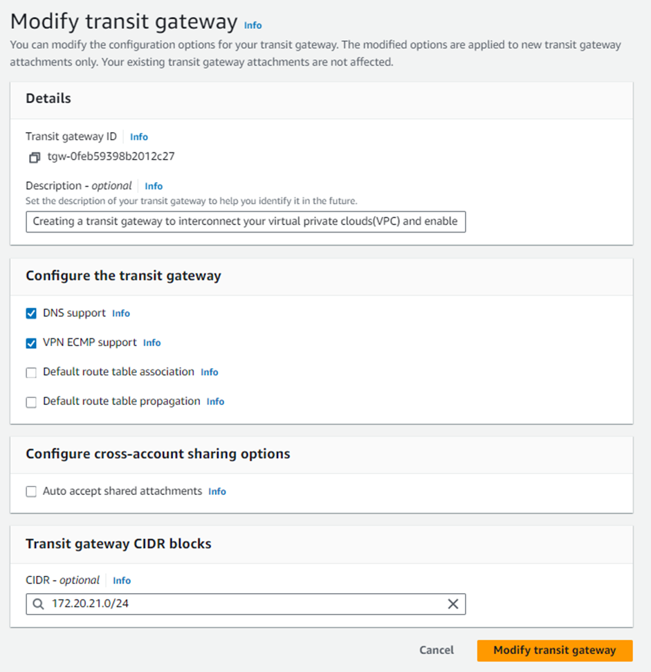
2. For the Transit gateway CIDR blocks, click the Add CIDR button and enter a suitable IPv4 network range with a /24 or larger CIDR block you wish to use for the GRE tunnels between the Sophos firewall nodes and the Transit gateway. Click Modify Transit Gateway to save the changes.
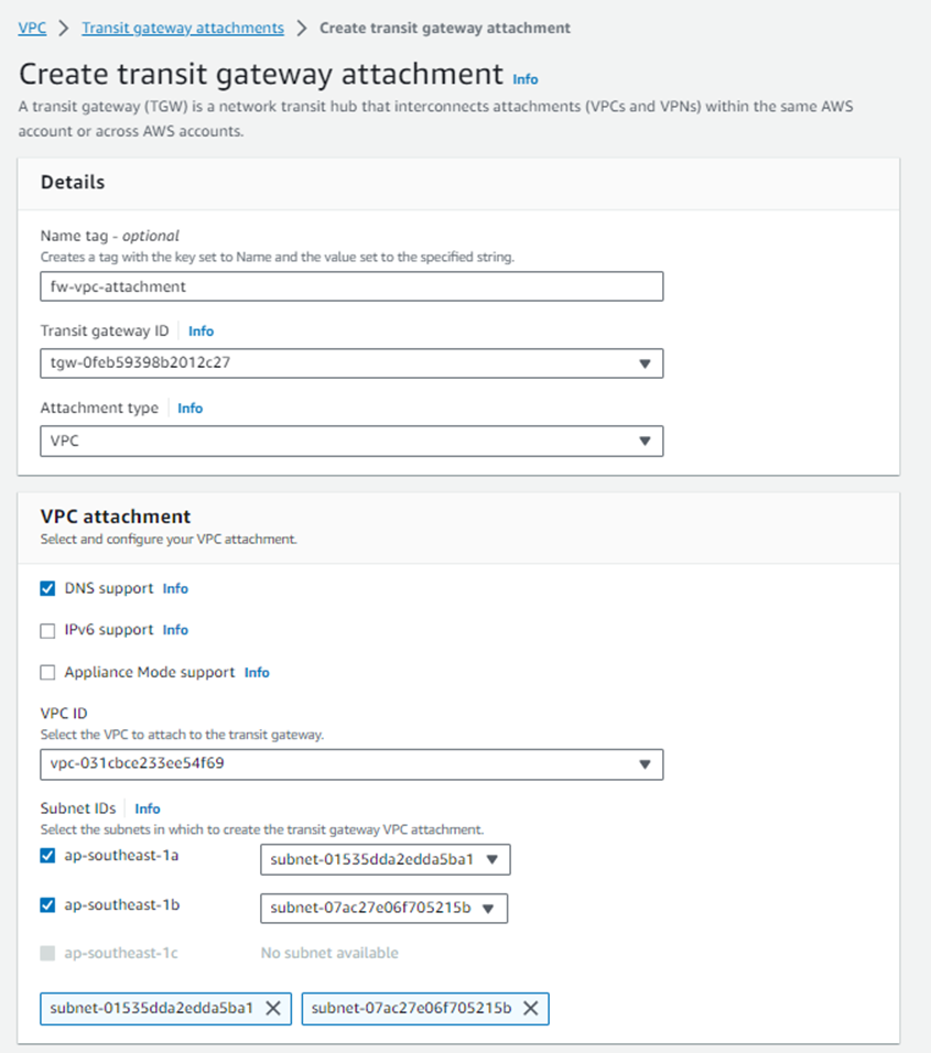
3. Navigate to Transit Gateway Attachments and click Create Transit Gateway Attachment.
Select the correct transit gateway from the drop-down menu and make sure that VPC is selected as the Attachment type.
Enter a name to help you recognize the connection in the Attachment Name tag.
Select the Sophos Firewalls’ VPC from the VPC ID drop-down menu and select the public-facing subnets of both the firewall nodes in the Subnet IDs section.
Click Create attachment to complete this transit gateway attachment creation process.
4. Similarly, create the Transit gateway attachments for LAN VPC and any other VPC also that needs connectivity with the Sophos Firewall instances via the AWS Transit gateway service

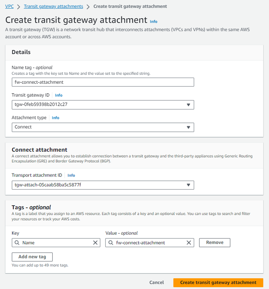
5. After all the transit gateway attachments have been created for the required VPCs, click Create Transit Gateway Attachment and select the same transit gateway ID. Make sure to select the Attachment type as Connect.
Enter a name that will help you recognize the connection in the Attachment Name tag.
Select the Sophos Firewalls’ local VPC from the Transport Attachment ID drop-down menu and click Create Transit Gateway Attachment.
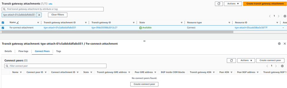
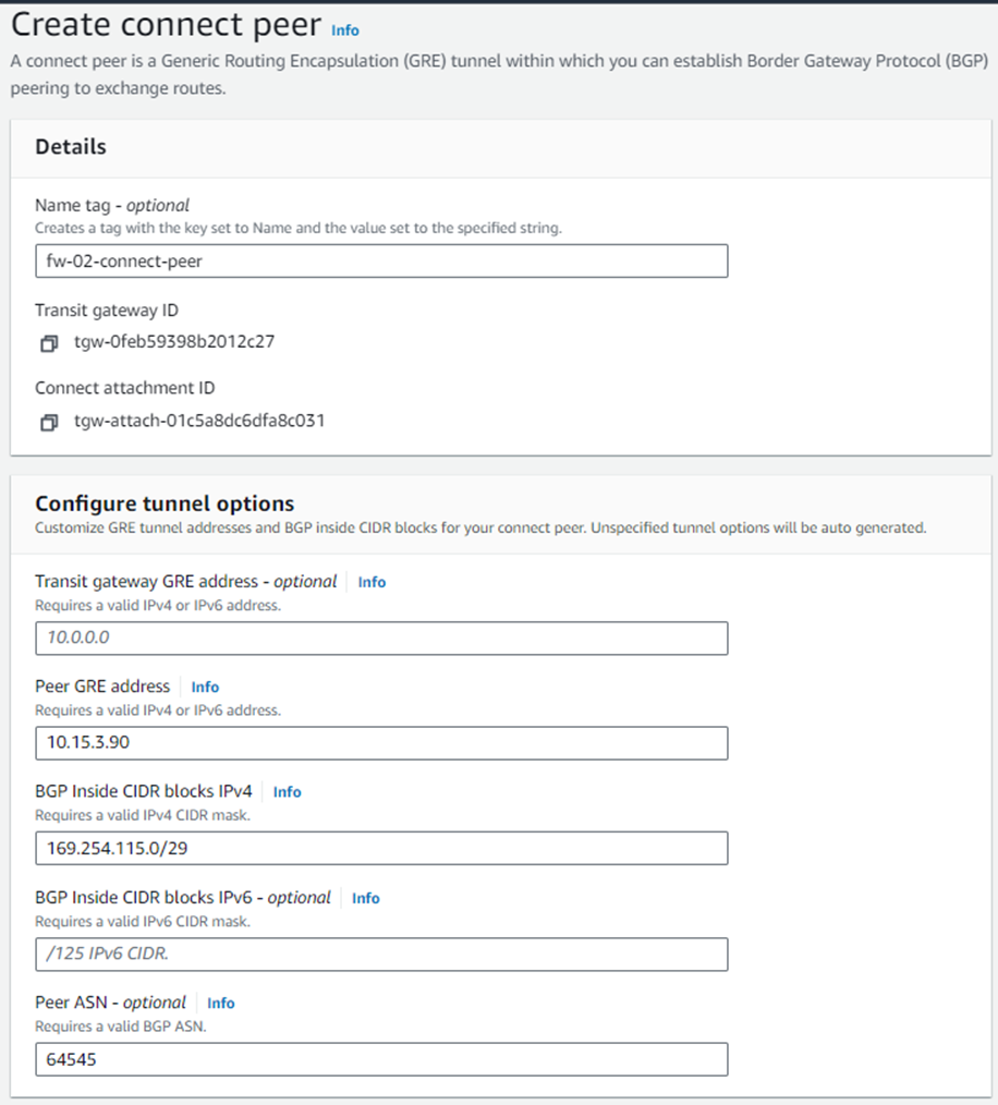
6. Select the newly created Connect attachment from the list, go to the Connect peers tab, and click Create Connect Peer.
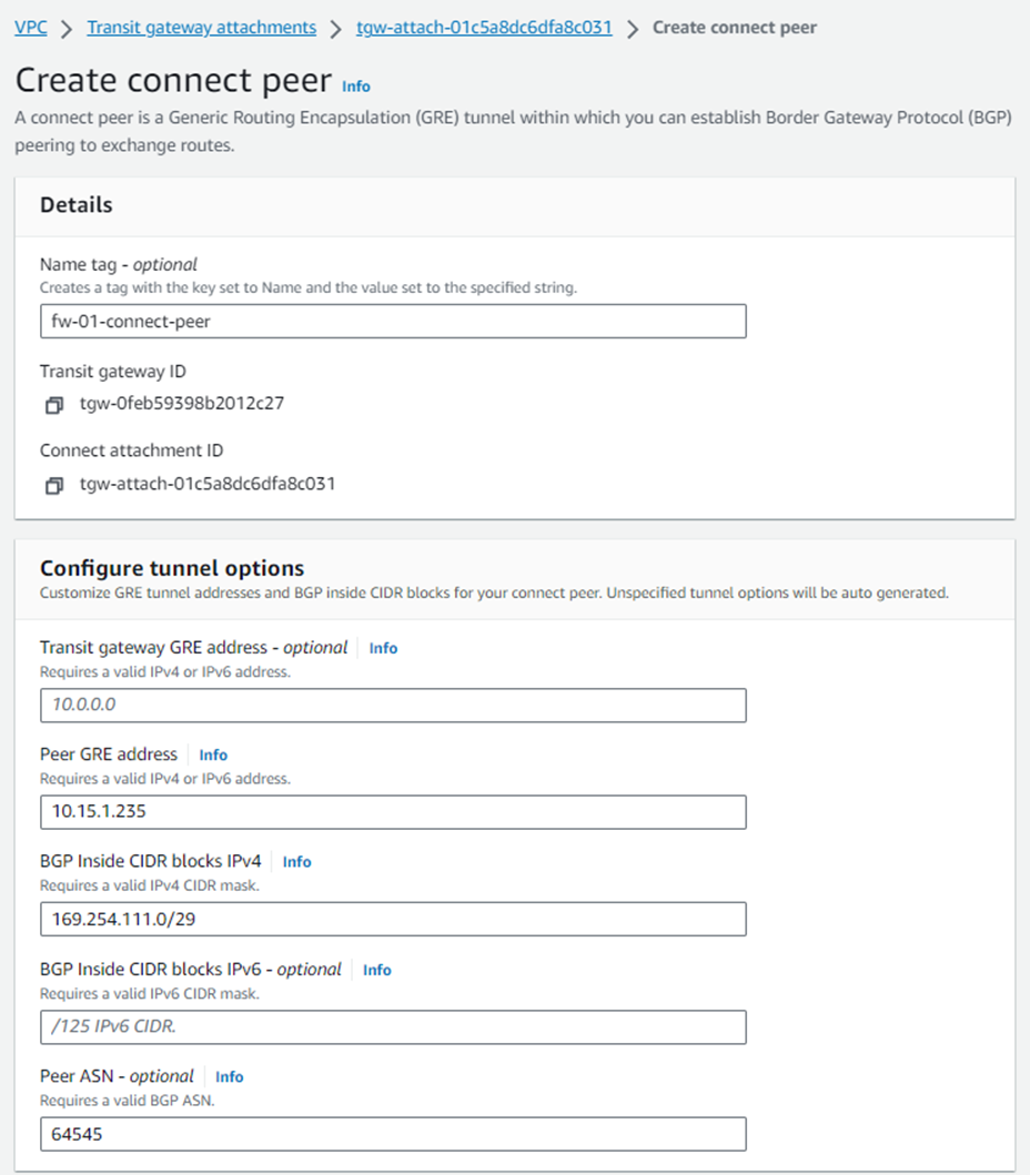
7. Enter an appropriate name in the Name tag field and keep the Transit Gateway GRE address as Auto-generated unless you wish to use a specific IP address in the CIDR block we previously attached to this transit gateway.
Enter the WAN network adapter IP address of Sophos Firewall 01 in the Peer GRE address field.
Set the IPv4 subnet you want to use inside the GRE tunnel by entering it in the BGP Inside CIDR blocks IPv4 field.
Note: This block needs to be exactly /29 large and part of the non-excluded sections of the 169.254.0.0/16 subnet. For more details, see: https://docs.aws.amazon.com/vpc/latest/tgw/tgw-connect.html
Peer ASN as the Sophos firewall's ASN used for BGP peering and finally click Create. This will be configured in the BGP section of Sophos firewall later.
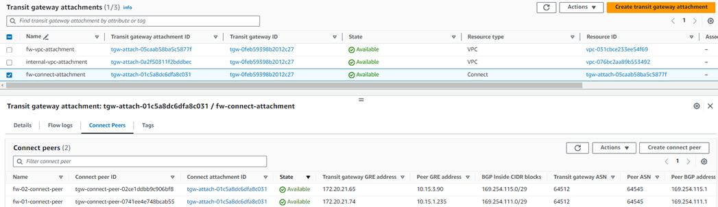
8. Create a Connect peer for Sophos Firewall 02 by following the steps mentioned in step #7.
Ensure that the Peer ASN value is the same as entered for Sophos firewall 01, so it’ll be implemented as an AA (Active-Active) deployment solution.
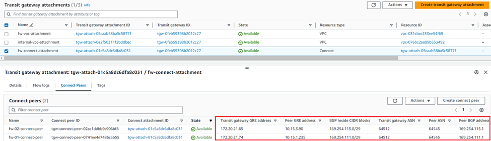
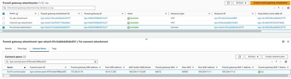
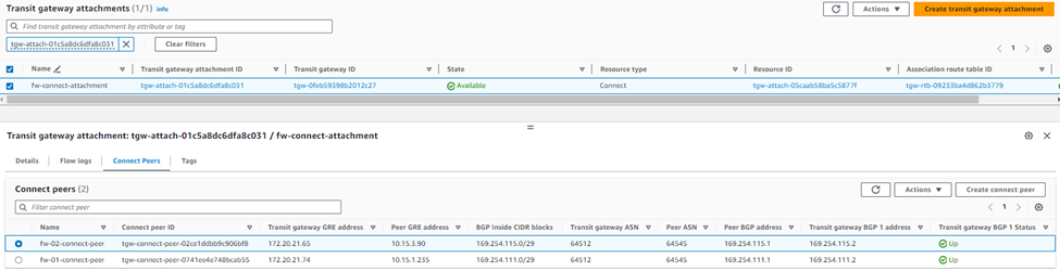
9. After both connect peers have been configured, it will show the GRE and BGP-related details, which can be used later as a reference while configuring GRE tunnel and BGP peering in both Sophos firewall nodes.
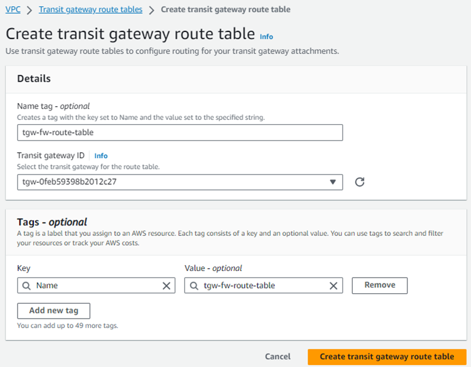
10. Navigate to Transit Gateway Route Tables and click Create Transit Gateway Route Table to create a new table.
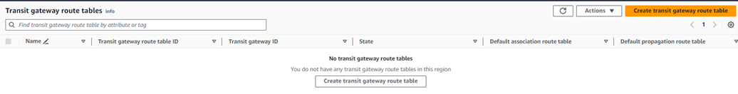
Enter a name for the table in the Name tag field, select the Transit Gateway used for the attachments earlier from the Transit Gateway ID drop-down menu, and click Create Transit Gateway Route Table.
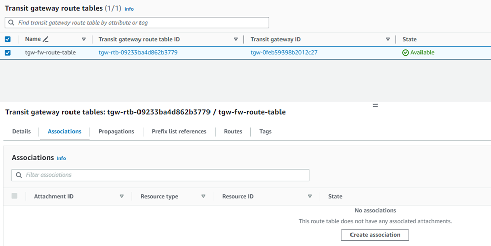
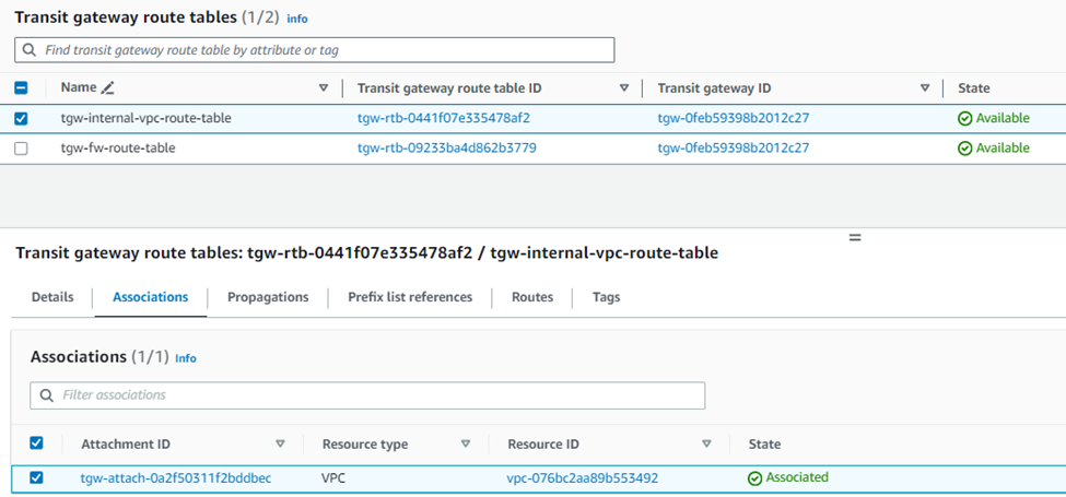
11. Select the Transit Gateway Route Table from the list, go to the Associations tab, and click Create Association.
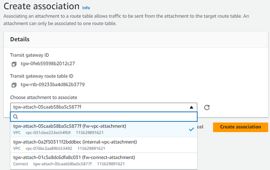
12. Select the VPC attachment for the Sophos Firewall created in step 3 and click Create association.
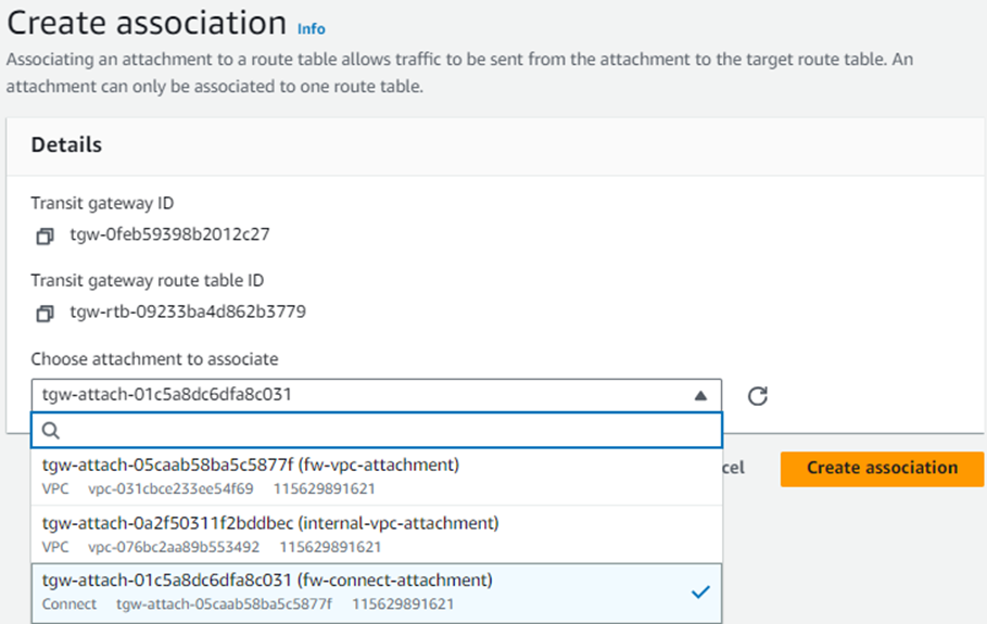
13. Similarly, create another association and select the firewall’s connect attachment created previously in step #5.
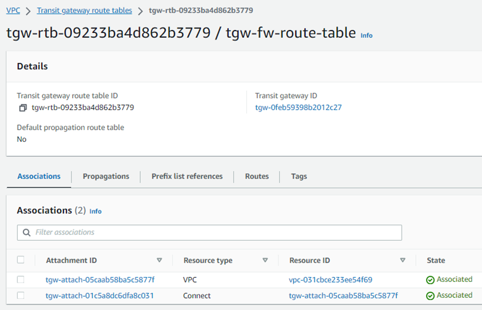
After this configuration, you’ll see two associations under this route table.
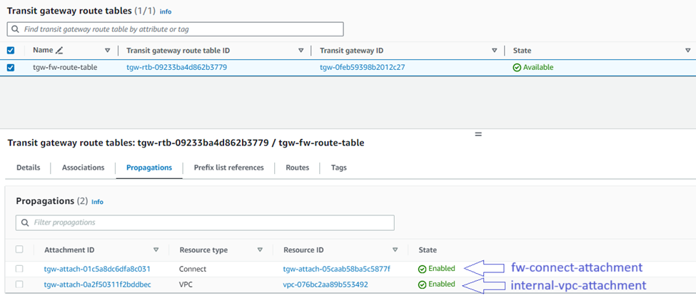
14. To turn on the Sophos Firewall to receive routing information from other VPCs, IPsec tunnels, and Connect tunnels, you’ll need to add them on the "Propagations" tab:
Repeat the above sub-steps for each additional attachment you wish to propagate to the Sophos Firewall via TGW.
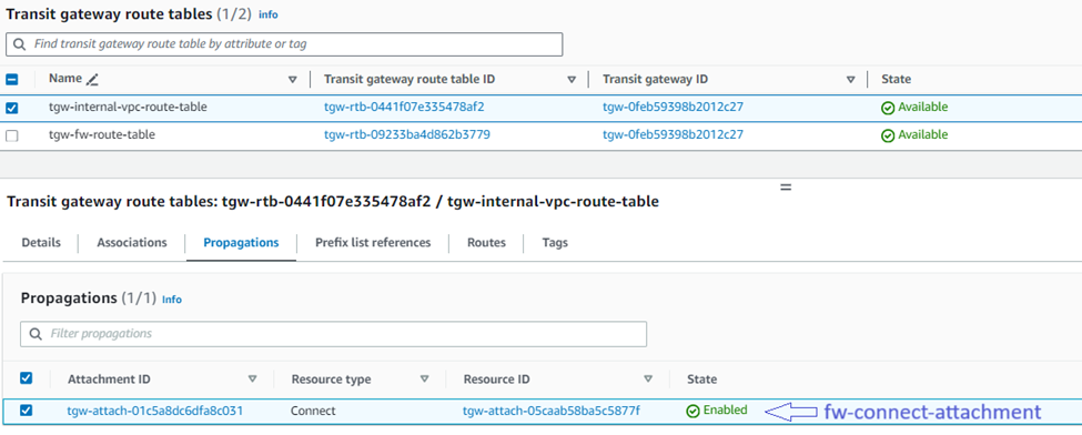
15. To turn on other VPCs, VPN, and Connect tunnels to receive routing information from the Sophos Firewall, you’ll need to:
Create a new transit gateway route table and select the internal LAN VPC.
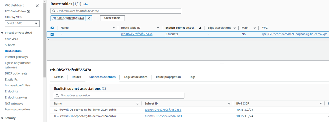
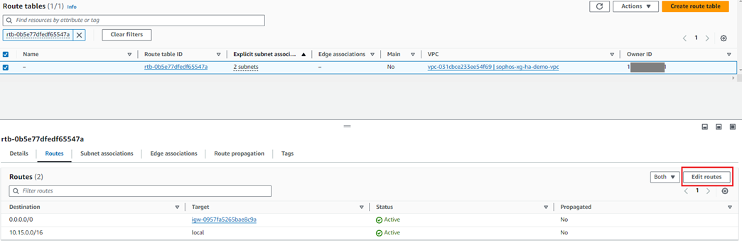
16. Navigate to the Virtual Private Cloud in the left-hand menu and select Route Tables.
Locate the route table associated with the Sophos Firewalls' WAN subnet
(This information can be found by selecting a route table associated with the firewall's VPC and checking the Subnet Associations tab).
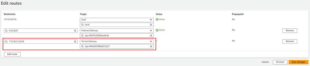
17. Click on the Routes tab and then click Edit Routes.
18. Click Add route and enter the Transit gateway CIDR.
Select the TGW created by CloudFormation in the Target list and click Save changes.
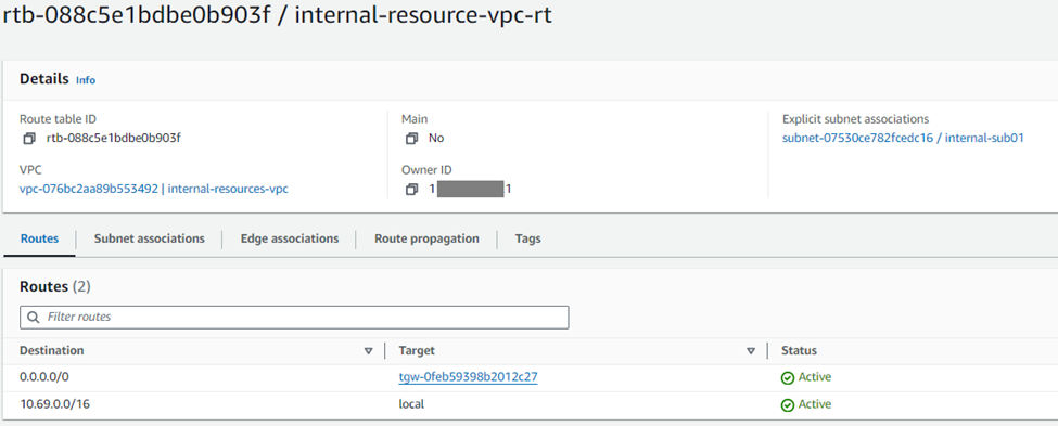
19. To force other subnets to route their traffic through the TGW, you must edit their subnet route tables to send relevant traffic to the gateway. To do so:
With the new Connect configurations created, the next step is configuring the Sophos Firewall nodes with the relevant GRE and BGP details.
I. In your AWS console, go to Services > VPC.
II. Navigate to Transit Gateway Attachments in the left-hand menu.
III. Select the Connect attachment for the Sophos Firewall node and go to the Connect peers tab.
IV. Note the address information in the following fields for both the entries that will be required to configure the Sophos firewall nodes:
a. Transit Gateway GRE address.
b. Peer BGP address.
c. Transit Gateway BGP 1 address.
1. In the AWS console, go to to Services > EC2 and click Instances.
2. Select the first Sophos firewall and copy the Elastic public IP address of the instance.
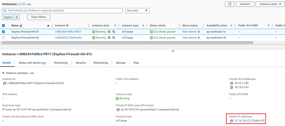
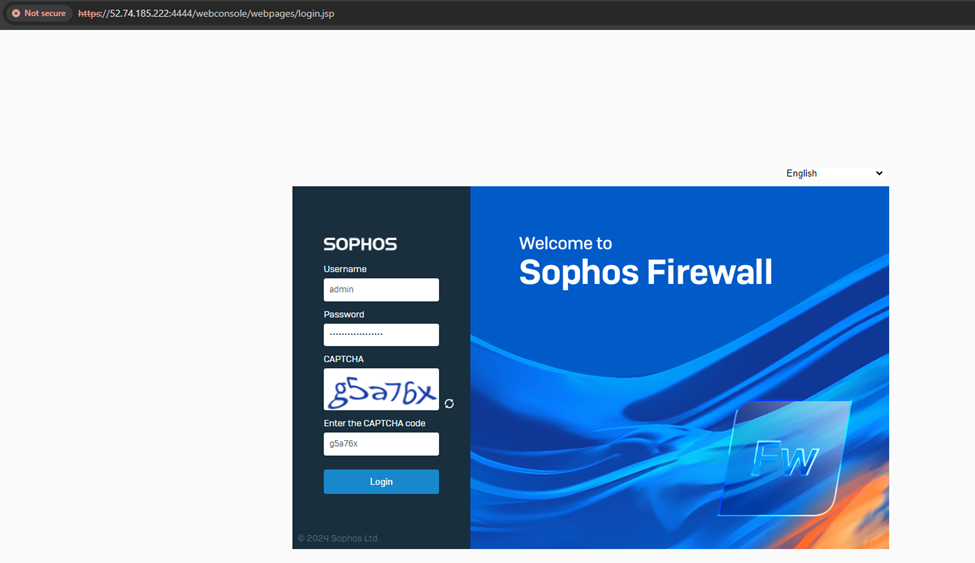
3. Open a new web browser tab and access the web console of the first firewall on HTTPS using the public IP copied in Step 2, appending port number 4444.
Enter the admin credentials and captcha, and click Login.
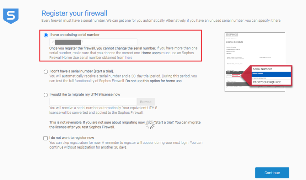
4. After logging into the device, it’ll go through the device claim(registration) process.
It’ll auto-detect the previous serial key entered during the CloudFormation deployment stage. Click Continue.
The next step is claiming the firewall in the Sophos Central account, so click the option Claim in Sophos Central.
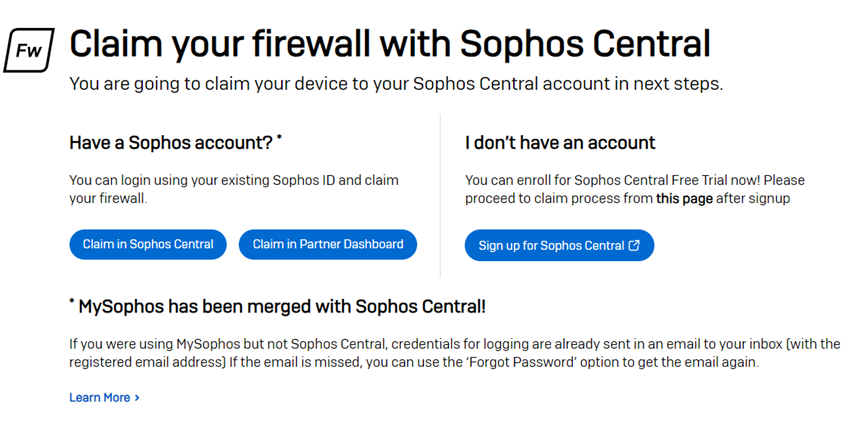
It’ll redirect to the Sophos Central Firewall licensing page, where you can claim a 30-day trial license for the firewall. Click Claim Firewall.
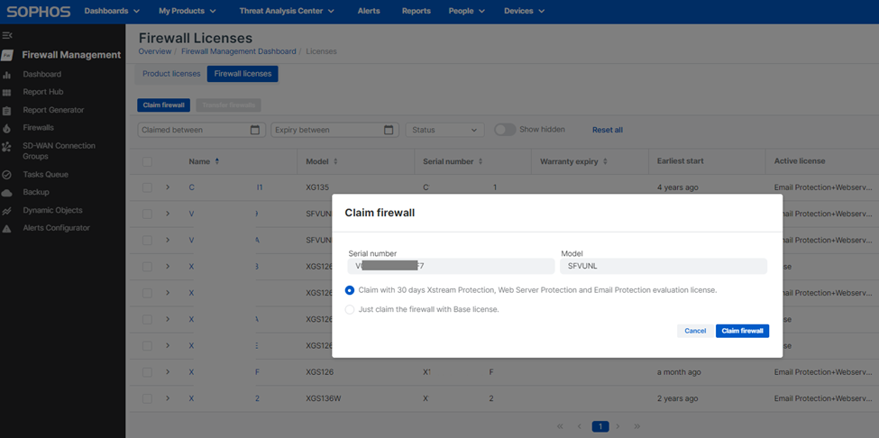
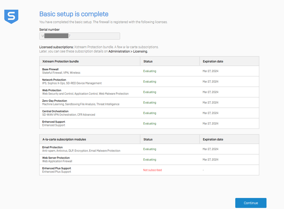
After this step, the license status of the firewall instance will be shown. Then click Continue to go to the Dashboard page.
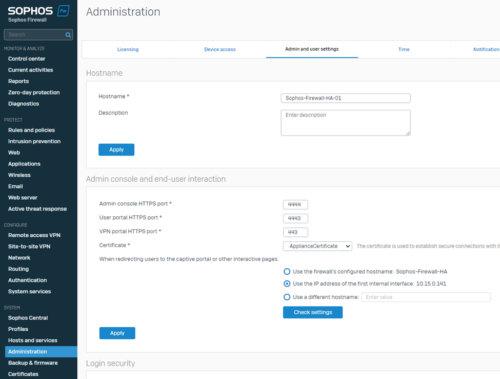
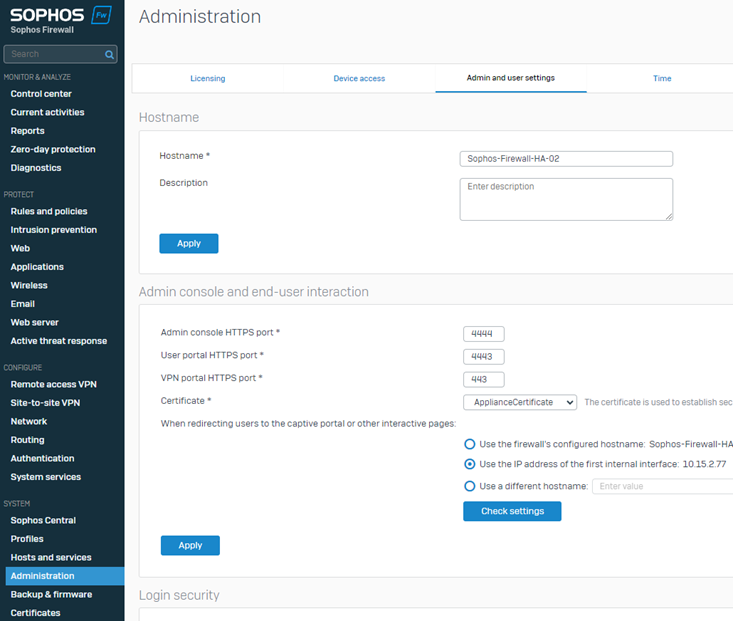
5. Navigate to SYSTEM > Administration > Admin and user settings and add -01 to the firewall's hostname to easily identify it from the Sophos Central Firewall management section.
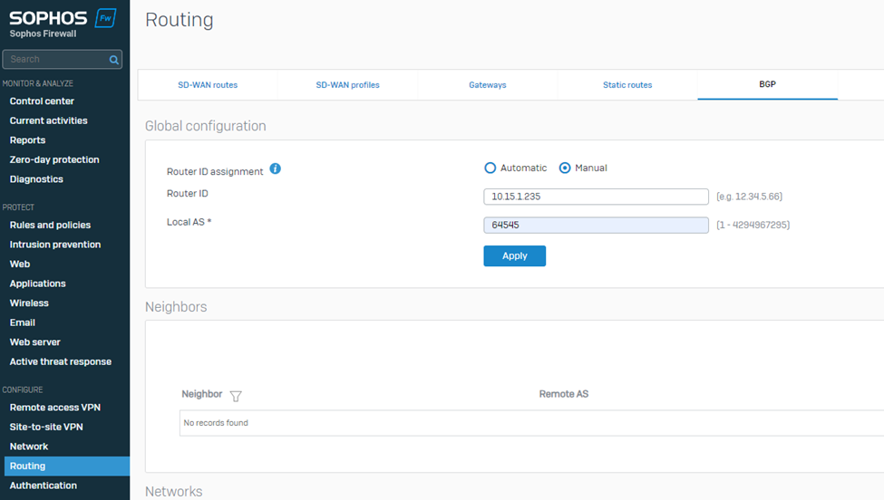
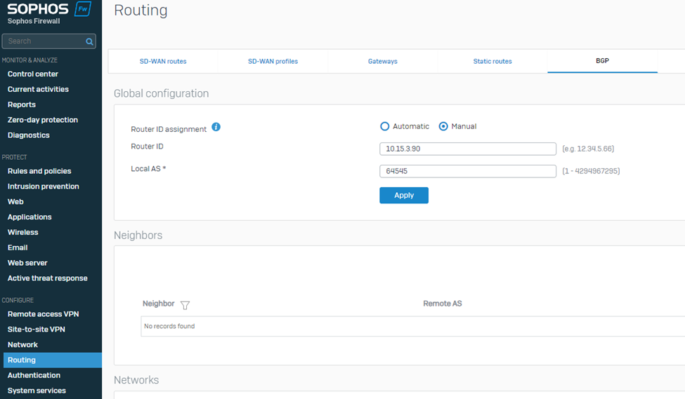
6. Navigate to CONFIGURE > Routing > BGP.
Select Route ID assignment as Manual.
Enter the Sophos Firewall's WAN adapter IP address in the Router ID field.
Enter the BGP Autonomous System number entered in step 7 of the previous section into the Local AS field.
Click Apply to save the configuration.
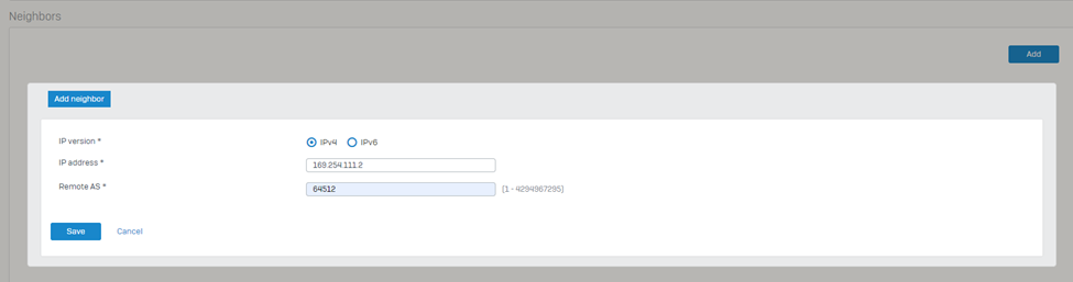
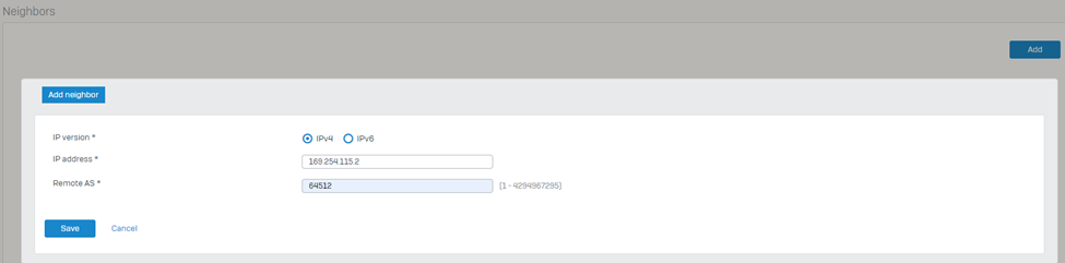
7. Navigate to the Neighbors section and click Add.
Select the IP version as IPv4.
Enter the IP address listed under Transit Gateway BGP 1 from step IV into the IPv4 address field.
Enter the Remote AS as the ASN used by the Transit Gateway.
Click Save to store the neighbor settings.
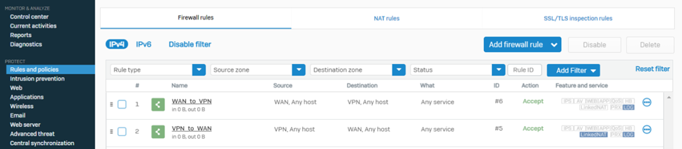
8. Navigate to PROTECT > Rules and policies > Firewall rules and make sure to create relevant firewall rules with action Allow so that the traffic can traverse successfully via the Sophos firewall

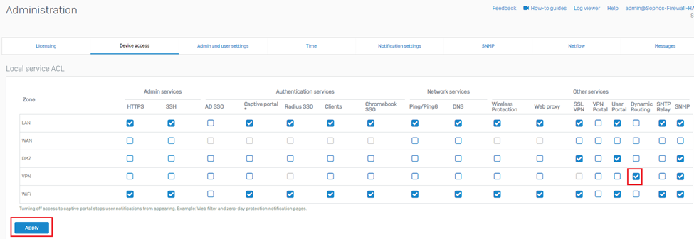
9. Navigate to System > Administration >Device access and turn on the Dynamic Routing option for the VPN zone.

10. Set up a remote shell session of SSH with the Sophos Firewall via the elastic public IP and sign in using the admin username and password.
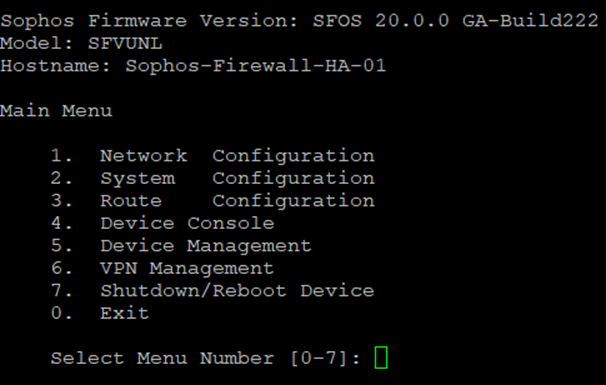
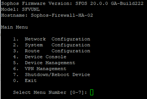
11. Select option 4. Device console.
Enter the following command (replacing the sections between <> with the details found in step IV): "system gre tunnel add name TGW01 local-gw PortB remote-gw <Transit Gateway GRE address> local-ip <Peer BGP address> remote-ip <Transit Gateway BGP 1 address>".
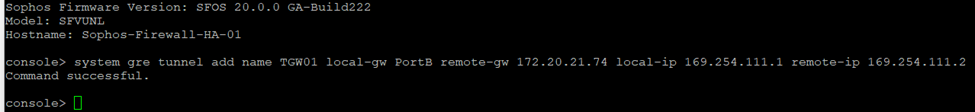
After executing the command, type exit to return to the main menu.
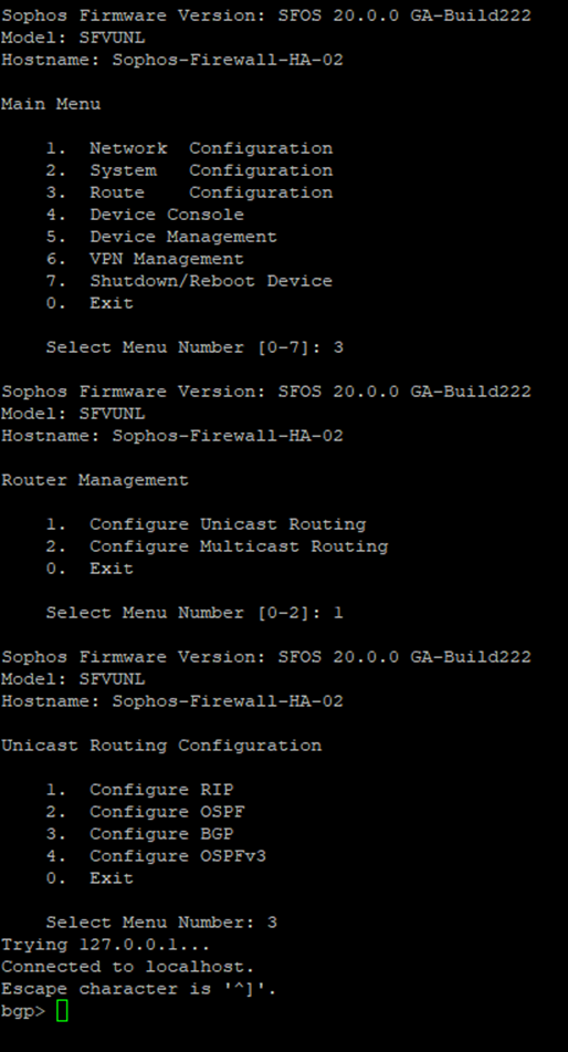
12. Select option 3. Route Configuration, followed by 1. Configure Unicast Routing, and 3. Configure BGP.
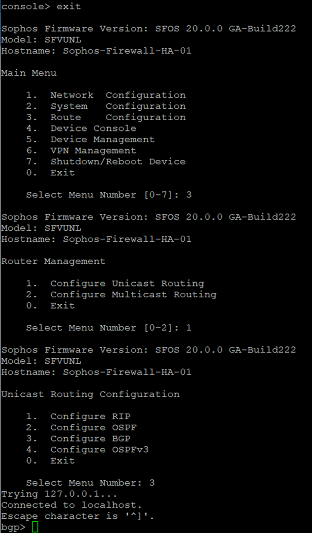
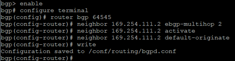
Enter the following commands to establish BGP neighbourship with Transit Gateway via the GRE tunnel:
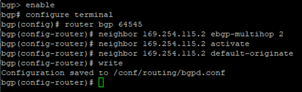
bgp> enable
bgp# configure terminal
bgp(config)# router bgp <This Firewall's ASN>
bgp(config-router)# neighbor <Transit Gateway BGP 1 IP> ebgp-multihop 2
bgp(config-router)# neighbor <Transit Gateway BGP 1 IP> activate
bgp(config-router)# neighbor <Transit Gateway BGP 1 IP> default-originate
bgp(config-router)#write
13. Type exit to return to the previous configuration level. Repeat until you return to the main menu.
Select 0. Exit and repeat until the SSH session is closed
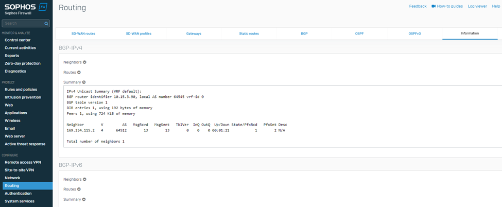
14. To verify whether the BGP neighbourship is established, check the BGP summary by navigating to CONFIGURE > Routing > Information > BGP.
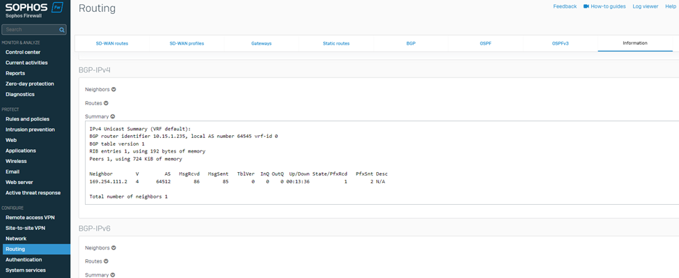
Similarly, on the AWS web console, it’ll show the status of the BGP1 IP address as Up.
This completes the configuration of Sophos Firewall 01.
15. Access the Sophos Firewall 02 using its elastic IP address and complete the claim(registration) process.
You can repeat instructions of steps #1 to 4 using Sophos Firewall 02 public IP.
16. Update the hostname of this firewall by adding -02.
17. Configure BGP on the Firewall 02 as follows:
18. Navigate to PROTECT > Rules and policies > Firewall rules and create relevant firewall rules with action Allow so that the traffic can traverse successfully via the Sophos firewall.
19. Navigate to System > Administration >Device access and turn on the Dynamic Routing option for the VPN zone.
20. Set up a remote shell session of SSH with the Sophos Firewall via the elastic public IP and sign in using the admin username and password.
21. Select option 4. Device console.
Enter the following command (replacing the sections between <> with the details found in step IV): "system gre tunnel add name TGW01 local-gw PortB remote-gw <Transit Gateway GRE address> local-ip <Peer BGP address> remote-ip <Transit Gateway BGP 1 address>"
![]()
After executing the command, type exit to return to the main menu.
22. Select option 3. Route Configuration, followed by 1. Configure Unicast Routing, and 3. Configure BGP.
Enter the following commands to establish BGP neighbourship with Transit Gateway via the GRE tunnel:
bgp> enable
bgp# configure terminal
bgp(config)# router bgp <This Firewall's ASN>
bgp(config-router)# neighbor <Transit Gateway BGP 1 IP> ebgp-multihop 2
bgp(config-router)# neighbor <Transit Gateway BGP 1 IP> activate
bgp(config-router)# neighbor <Transit Gateway BGP 1 IP> default-originate
bgp(config-router)#write
23. Type exit to return to the previous configuration level. Repeat until you return to the main menu.
Select 0. Exit and repeat until the SSH session is closed.
24. To verify whether the BGP neighbourship is established, check the BGP summary by navigating to CONFIGURE > Routing > Information > BGP.
Similarly on the AWS web console, it’ll show the status of BGP1 IP address as Up.
This completes the configuration of Sophos Firewall 02.
After deployment is complete, the network load balancer used by the Active-Active deployment will be configured to perform a health check on the firewall nodes using port TCP 4444.
Since this port is part of the management port range affected by the Trusted Network security group, health checks are expected to fail because the load balancer is not part of said trusted network range.
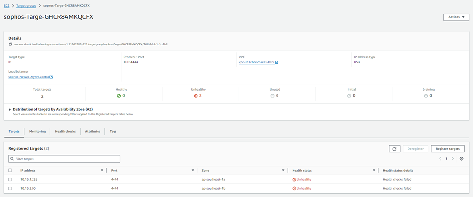
This is intentional as it avoids exposing the management ports or the load balancers to unintended traffic.
To make the AWS Network Load Balancer functional, we recommend modifying the existing health check to match the service port used by the content published on the firewall.
For example, if the WAF (Web Application Firewall) feature is used to accept traffic on port TCP 443, we recommend setting the load balancer's health checks to use the same port. This ensures that service delivery capabilities and health check status are aligned, and failed firewall nodes are automatically removed from service.
For the AA (Active-Active) scenario, you must apply source NAT(MASQ) to inbound traffic for any DNAT rule allowing traffic from the WAN zone into the environment. This enables the TGW to route traffic back to the correct Sophos Firewall instead of balancing the request over all available nodes, preventing asymmetric routing.
DNAT rule can be created from the Sophos Central Firewall group and automatically pushed to both firewall nodes.
For the demonstration purposes, we’ll create a DNAT rule to open RDP port 3389 as follows:
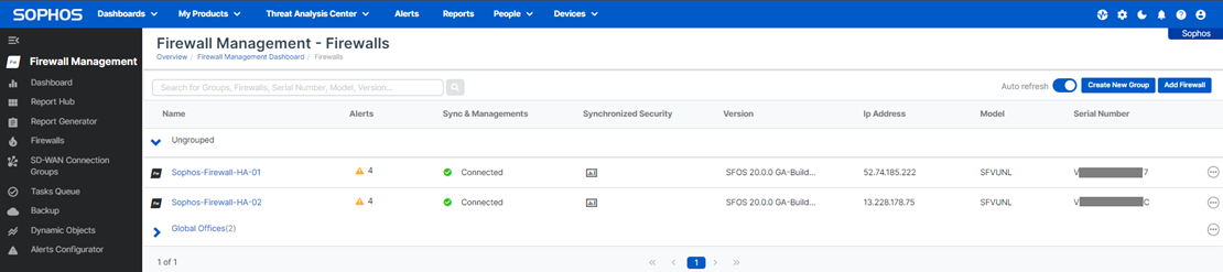
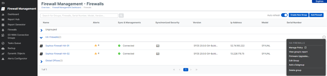
1. log in to your Sophos Central account and then go to to My Products > Firewall management > Firewalls, and you’ll see both the firewall nodes under the Ungrouped section.
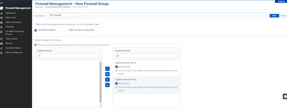
2. Click on the Create New Group button, enter the name of the firewall group, select Use Sophos default template, and then select both the firewall nodes from the Available Firewalls column and add them to the Assigned Firewalls column.
Ensure that the Skip full sync tick mark is turned on for both the firewall nodes and hit the Save button.
3. Now, it’ll show both the firewall nodes placed under the new group. Click the ellipsis icon at the right side of the group and click Manage Policy.
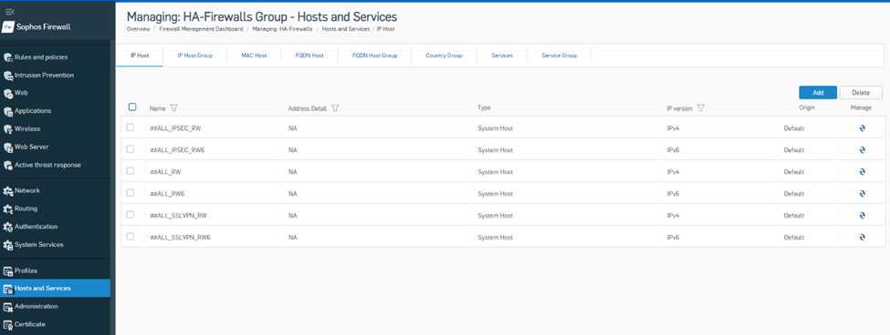
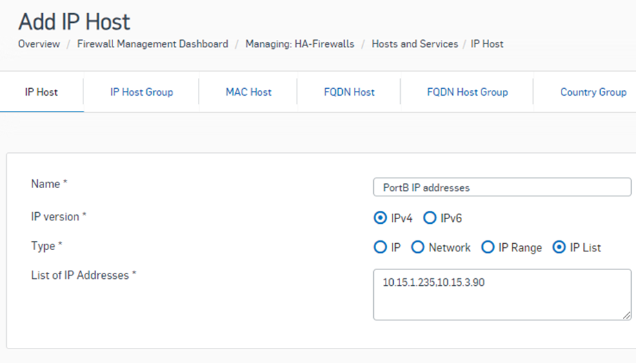
4. This will open a new web browser tab and show the group policy configuration page. Go to to Hosts and Services > IP Host and click the Add button.
Create a new IP Host object with the Type selected as IP List. Enter the private IP address of PortB of both firewall nodes separated by ‘,’ and hit the Save button.
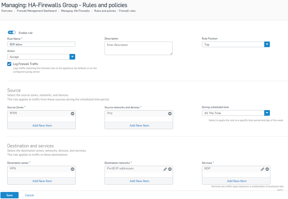
5. Now go to Rules and Policies> Firewall rules and click Add Firewall Rule > New Firewall rule option.
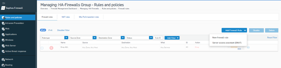
Enter the name of the firewall rule, Rule Position as Top, Action as Accept, logging option turned on,
Source zones as WAN, Source networks as Any,
Destination zones are VPNs, destination networks are newly created IP host objects, and services are used as RDPs configured for Port 3389. Then, hit the Save button.
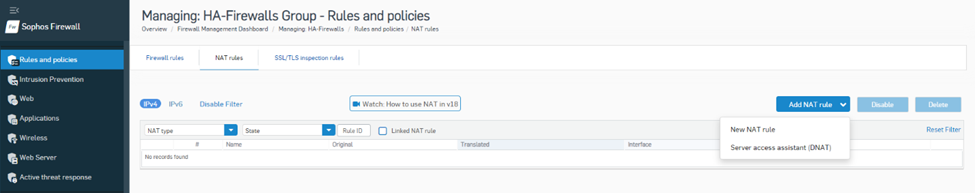
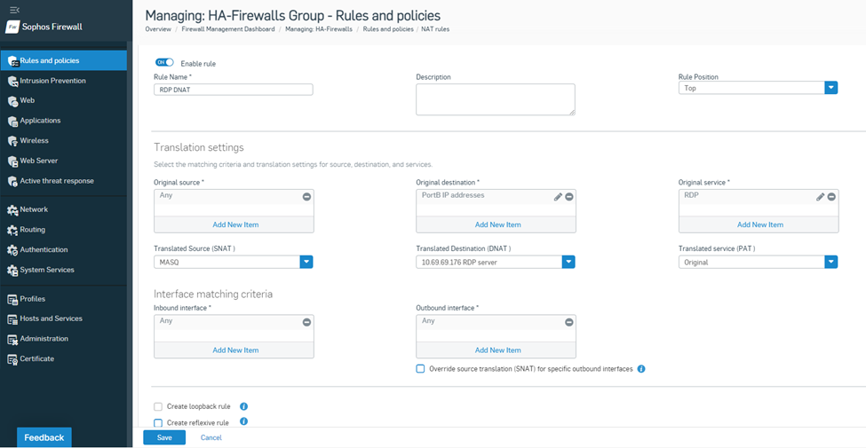
6. Navigate to Rules and Policies> NAT rules and click Add NAT rule > New NAT rule.
Enter the name of the NAT rule, Rule Position as Top, Action as Accept,
Original Source as Any, Original Destination as IP host object, and Original service as RDP,
Translated Source as MASQ, Translated Destination as the actual private IP of RDP server, and Translated service as Original,
Inbound and Outbound interfaces can be kept as Any, and then hit the Save button.
With this configuration in place, both the firewalls will have one firewall rule and one NAT rule that will allow RDP traffic from the internet to be forwarded to the TGW. The source IP of that traffic will be Source NATed with PortB private IP to avoid asymmetric routing.
As mentioned in the introduction discussing the models, east-west traffic requires additional provisions - similar to the abovementioned DNAT considerations.
This is needed as the TGW uses the state-unaware BGP Equal Cost Multi-Pathing (ECMP) algorithm to distribute traffic over the available firewall nodes, which could cause asynchronous routing scenarios in which return traffic can't be guaranteed to return to the firewall node that processed the outgoing traffic, resulting in broken TCP sessions.
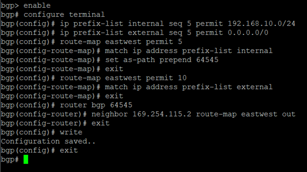
Since most companies don’t want to apply source NAT (or any NAT for that matter) on traffic flowing between internal sources, you will need to enable BGP path prepending on the Sophos firewall 02 node to raise its path cost.
This causes the TGW to no longer populate both firewall nodes as viable next-hop targets into the propagated route tables, preferring to only populate the one with the lowest path cost, which ultimately enables the firewall nodes to act as an Active-Active pair for inbound and outbound north-south traffic, while operating like an active-passive HA setup for east-west traffic.
The steps involved are as follows:
20. Go back to the interactive menu by entering “exit” followed by <enter>
21. End the SSH session by entering “0”, “0”, “0”
This concludes the Sophos Firewall AA deployment instructions in this document.
To use the security and scanning features of Sophos firewall, feel free to refer to the online documentation repository available via the following link:


