


Sophos Remote Ethernet Device (RED) is a small network appliance, designed to be as simple to deploy as possible. Its main purpose is to provide a secure tunnel from its deployment location to a Sophos UTM firewall.
There is no user interface on the RED appliance. It is designed to be fully configured and managed from a Sophos UTM. RED devices can be shipped to a remote site, connected to any DHCP connection to the internet, and be fully configured by a remote administrator with no prior knowledge of the site, and no need to walk local personnel through technical setup steps.
This guide details how to setup Sophos RED in each of its operational modes, and outlines common troubleshooting steps to resolve connection issues.
The following sections are covered:
- RED technical overview
- Chapter 1: RED operation modes overview
- Chapter 2: RED setup
- Chapter 3: Advanced operations
- Chapter 4: Troubleshooting
- Related information
Applies to the following Sophos products and versions
Sophos RED,
Sophos UTM
RED technical overview
When a RED is configured in a Sophos UTM firewall, the configuration options chosen by the administrator are uploaded to the Sophos provisioning servers. The configuration is little more than the following items:
- Address of the firewall to which it will tunnel
- WAN Uplink Mode (DHCP, Static IP)
- Tunnel operation mode (Standard)
- If static uplink mode is chosen, RED WAN address settings (Address, Netmask, Default Gateway, and DNS server)
- Optionally, mobile broadband connection settings for RED v2 and above hardware
- Unlock code
The unlock code is not stored on the RED appliance, but is used to prevent a RED that is in use from being accidentally or maliciously redirected. The correct unlock code must be supplied for the provisioning servers to accept new configuration for a RED. Initially, the unlock code is blank, until a RED has been connected to a UTM once. The first time a RED device is configured in a UTM, the unlock code should be left blank. Every time a RED is connected to a new UTM, the old unlock code must be entered in the new UTM to move the RED. Once the settings are pushed to the provisioning server, a new unlock code is issued, and displayed in the WebAdmin of the UTM.
The provisioning servers store the configuration provided by the administrator, on a centrally reachable set of servers. RED devices are able to be centrally configured due to this mechanism. When a RED device has no configuration, or the configuration it has is unsuccessful, it will look to the provisioning servers for updated instructions. A DNS lookup of red.astaro.com will return the closest provisioning server, which it will then securely connect to, and check for new instructions from the provisioning servers. As long as a RED has a working configuration, it will not check back with the provisioning servers again.
Chapter 1: RED operation modes overview
RED can operate in several modes. This section will help to understand how each of these modes operate, and help you to decide which modes are best suited to which circumstances.
The deployment helper tab in the UTM WebAdmin can assist in setting up new appliances very rapidly. It does much of the work necessary to fully enable a RED tunnel to be active, and able to allow traffic. In the following examples, we will not use the deployment helper, but instead walk through all steps manually, that the deployment helper would complete automatically. These scenarios will reference two different Sophos devices. One is the RED appliance, which sits at the remote location. The other is the UTM appliance with which the RED device will establish a tunnel. Both will have a connection to the internet, as shown in figure 1.
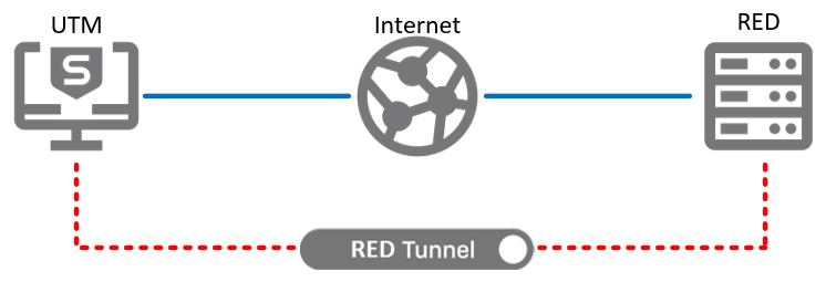
Figure1: General RED layout
Standard/Unified mode
This is the most commonly used mode. In this mode, we expect that the remote network will be fully managed by the UTM, through the RED. DHCP may be offered for the remote LAN by the UTM, and the RED may be the only device connecting the LAN to the Internet. While another router may sit in front of the RED, there is not a parallel path around the RED to the internet.
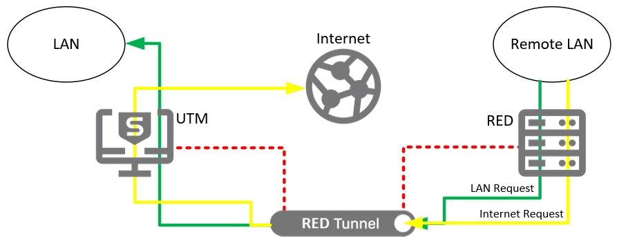
Figure 2: RED used in Standard/Unified mode
Figure 2 illustrates the flow of data in this operational mode. All traffic from the remote LAN will pass through the RED tunnel, whether it is heading for the local LAN, or the Internet. This allows the UTM to allow or deny requests in exactly the same manner as it does for traffic coming from the local LAN. Traffic between local and remote LANs can be blocked or allowed just by using firewall rules on the UTM. Web traffic can be filtered using the web security module, and applications such as Skype or BitTorrent can be controlled for remote LAN users, just as they can be for LAN users. This provides the highest level of security and manageability for remote networks. Its biggest drawback is the increased bandwidth requirements it may place on the UTM’s internet link. Since all internet traffic from the remote LAN also uses internet bandwidth at the UTM, the internet bandwidth at the UTM must be large enough to service requests from both its own local users, and all remote RED users. The RED 10 appliance is capable of tunneling data at up to 30 Mbps.
In the event that the RED loses contact with the UTM, and the tunnel fails, the RED will fail closed. Remote LAN users will lose access to the internet as well as to the UTM LANs until the tunnel can reconnect.
Standard/Split mode
Standard/Split mode is physically similar to Standard/Unified mode. We expect that the remote network may be managed by the UTM, and UTM may provide DHCP to the remote LAN. Also, the RED is most likely the only device between the LAN and the internet. However, only traffic for selected networks is sent through the tunnel. All other traffic is sent directly out the local internet connection. The RED will masquerade outbound traffic to come from its public IP address. This minimizes bandwidth usage over the tunnel, and lightens the bandwidth requirements on the UTM, but it also reduces the manageability of the remote network substantially. Traffic to or from the internet cannot be filtered or protected from threats. Security can only be applied between the remote and local LANs.
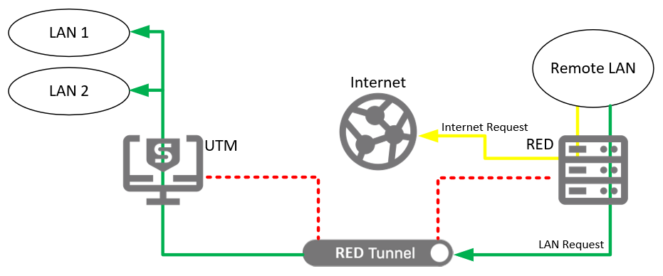
Figure 3: RED used in Standard/Split mode
In the event that the RED loses contact with the UTM, and the tunnel fails, the RED will fail closed. Remote LAN users will lose access to the internet as well as to the UTM LANs until the tunnel can reconnect.
Transparent/Split mode
In this option, the UTM is not expected to manage the remote network. It will be connected between the remote LAN and the remote LAN’s gateway, and it will expect to receive an address on the remote LAN via DHCP. Similar to the Standard/Split option, only traffic destined for certain networks will be sent down the tunnel. In this case, the RED does not act as the gateway, but since it is in-line with the gateway, it can transparently redirect packets down the tunnel.
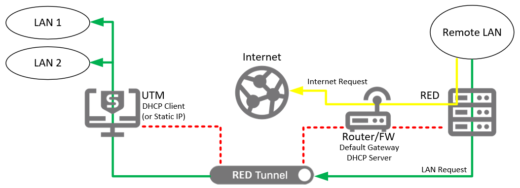
This option requires no reconfiguration of the remote network, but it does not allow any management of the remote LAN. It can only provide security between the remote LAN, and any local subnets which are accessible through the tunnel. Also, in the event that the tunnel should go down, the internet will also go down for any devices behind the RED.
Chapter 2: RED setup
Basic setup instructions
This section will outline the basic steps required to manually add a new RED to a UTM. In some cases, more detailed setup options may be desired, but this will be outside of the scope of this document.
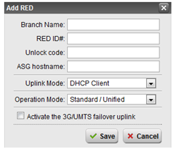
Figure 4: Adding a RED appliance
Adding a RED to the UTM
- In the WebAdmin, select the RED Management menu option.
- Select the Device Configuration tab.
- Click the Add RED button.
- Enter a descriptive branch name in the Branch Name field.
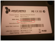
- Enter the RED ID. The ID can be found on the bottom of the RED appliance.
- If the device has been setup before, an Unlock Code will be needed to save the configuration. This will be shown in the WebAdmin of the UTM that the RED is currently joined with.
- Enter the public IP address or hostname of this UTM. The RED will use this address to locate the UTM across the internet. Be sure that a publicly resolvable fully qualified domain name or public IP address is used.
Note: It is strongly recommended that the Uplink Mode remain set to DHCP client if at all possible. Static address should only be chosen if there is no option for DHCP. When setting a static IP, bear in mind that the RED must connect to a DHCP network at least once, to download its settings. If static address is chosen, then additional fields will appear for IP address, Netmask, Gateway IP, and DNS servers.
- Choose the Operation Mode you wish to enable. Refer to chapter 1 for the explanations of each operating mode. Depending on your mode choice, there may be additional instructions.
- Standard/Unified
No additional steps - Standard/Split
Add all network ranges that should be accessible over this RED link to the Split networks list. - Transparent/Split
Add all network ranges that should be accessible over this RED link to the Split networks list.
- Standard/Unified
- Click Save.
Configuring the RED interface on the UTM
Follow this section for all setup modes:
- In the WebAdmin, select the Interfaces & Routing menu, then the Interfaces submenu.
- Click the New Interface button.
- Enter a Name for the new interface.
- Depending on the RED operation mode, the interface Type choice may be different:
- Standard/Unified or Standard/Split
Choose Ethernet Standard. - Transparent/Split
Choose Cable Modem (DHCP).
- Standard/Unified or Standard/Split
- In the Hardware list, select the red hardware interface created for the new RED. It will be named similar to reds#, where the # is the next available number. The first RED will be called reds1. It will also list the (Branch Name) given in step 4 of Adding RED to the UTM.
- Configure the remaining address parameters as necessary. The address settings chosen will be controlled by the UTM, but will participate in the remote LAN.
- Standard/Unified or Standard/Split
- Choose the first address in a new, unique private subnet. Be sure it does not conflict with any other networks that you may access, and within one of the designated private IP ranges. Assume that 192.168.44.0/24 is a unique subnet, and does not conflict with any other subnets that you use. We will use this as the example for configuring the interface, but any suitable network range can be used instead of this value.
- The IPv4 Address would be set to 192.168.44.1.
- The Netmask would be set to /24 (255.255.255.0).
- IPv4 Default Gateway would not be checked.
- Click Save.
- IPv6 related options are not discussed in this guide.
- Enable the newly created interface.
- Transparent/Split
- Address settings will be received through DHCP.
- Standard/Unified or Standard/Split
Creating a Masquerading rule
Follow this section for Standard/Unified mode. This section can be skipped for other modes if none of the Split networksare accessed over the internet.
If traffic from the remote LAN will pass through the RED tunnel and out to the internet, you will need to create a Masquerading rule. The instructions below will create a rule specifically for traffic from the remote LAN.
- In the WebAdmin, select the Network Protection menu option.
- Select the NAT sub menu item.
- Click New Masquerading Rule.
- Click the yellow folder icon next to the Network field to show the left-hand Networks menu.
- At the top of the Networks menu, select the drop down menu, and choose Interface Networks.
- Find the (Network) definition for the RED interface created in the basic setup, and drag it into the new masquerading rule Network field.
- Leave the Position field at its default value.
- Set the Interface field to External. If your internet facing interface is named something other than External, choose that name instead.
- Leave the Use address field at its default value.
- Click Save.
- Enable the new Masquerading rule.
Creating firewall rules
Follow this section for all operation modes.
Creating firewall rules can be as simple or as complex as you require, but explaining how to create detailed firewall rules is outside of the scope of this article. In this example we will create one rule allowing the remote LAN access to both the internet, and any local networks. It is assumed that you will create more restrictive rules if tighter security is required.
- In the WebAdmin, select the Network Protection menu option.
- Select the Firewall sub menu item.
- Click New Rule.
- Click the yellow folder icon next to the Sources field to show the left-hand Networks menu.
- At the top of the Networks menu, select the drop down menu, and choose Interface Networks.
- Find the (Network) definition for the RED interface created in the basic setup, and drag it into the new masquerading rule Sources field.
- Leave Services set to Any.
- Leave Destinations set to Any.
- Leave Action set to Allow.
- Click Save.
Creating a DHCP Server
Follow this section for Standard/Unified and Standard/Split operation modes.
If the UTM is managing the remote network, as would most likely be the case in Standard/Unified or Standard/Split modes, then the UTM should have a DHCP server configured.
- In the WebAdmin, select the Network Services menu option.
- Select the DHCP sub menu item.
- Click New DHCP Server.
- Choose the RED interface from the Interface drop down menu.
- Click Save.
Next, the DNS relay will need to allow queries from the remote LAN.
- In the WebAdmin, select the Network Services menu option.
- Select the DNS sub menu option.
- Click the yellow folder icon at the top of the Allowed Networks list to show the left-hand Networks menu.
- At the top of the Networks menu, select the drop down menu, and choose Interface Networks.
- Find the (Network) definition for the RED interface created in the basic setup, and drag it into the Allowed Networks list.
- Click Apply.
Deployment scenarios
-
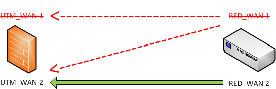
UTM hostname = Failover
-
RED uplink = Failover
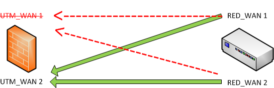
The RED establishes a connection between RED_WAN1 and UTM_WAN1.
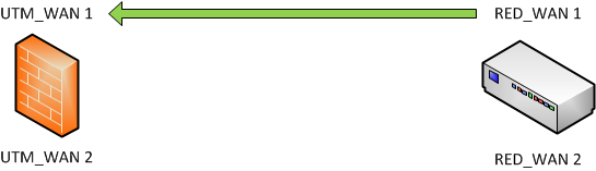
If UTM_WAN1 is down: RED_WAN1 will connect to UTM_WAN2
If UTM_WAN1 and RED_WAN1 is down: RED_WAN2 will connect to UTM_WAN2
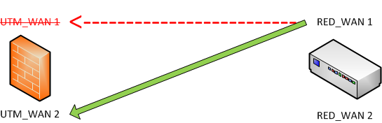
-
UTM hostname = Balancing
-
RED uplink = Failover
The RED establishes a connection between RED_WAN1 and UTM_WAN1 / UTM_WAN2
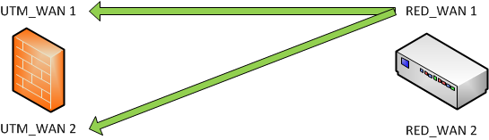
If RED_WAN1 is down: RED_WAN2 will connect to UTM_WAN1 / UTM_WAN2
-
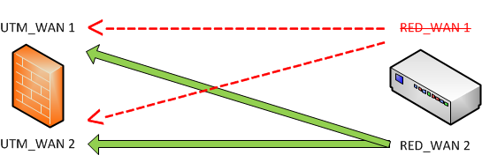
UTM hostname = Failover
-
RED uplink = Balancing
The RED establishes a connection between RED_WAN1 / RED_WAN2 and UTM_WAN1
If UTM_WAN1 is down: RED_WAN1 / RED_WAN2 will connect to UTM_WAN2
-
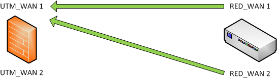
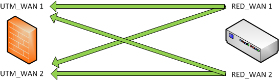
UTM hostname = Balancing
-
RED uplink = Balancing
The RED establishes a connection between RED_WAN1 / RED_WAN2 and UTM_WAN1 / UTM_WAN2
Note: If any interfaces go down, the interface will be checked until it is working again. The connection will be restored to the original interface if it becomes available again.
Chapter 3: Advanced operations
Manual/Split setup
This is not an option that can be chosen when configuring the RED, but is implemented mostly through physical configuration. This mode is not unlike Transparent/Split mode, but it allows the tunnel to go down without also disabling local internet access. In this scenario, the red is configured in Standard/Unified mode, but is not placed in front of the remote LAN. It is connected as an alternate gateway on the remote LAN, and routes must then be added on the existing default gateway to access remote networks behind the RED.
The WAN port is plugged into the same LAN switch that LAN clients are connected to, and once the RED receive its mode configuration, you then connect a LAN port to the same LAN switch.
The setup is marginally more physically complex than other modes, but is logically simpler, and allows for tunnel or RED hardware failure, without disrupting normal internet traffic.
Bridged RED setup
When dealing with a large number of RED devices, it may be simpler to treat all remote RED networks as a single LAN. The UTM supports creating a single bridge interface, bridging any number of NICs. If you have not setup a bridge interface already, you may bridge more than one RED connection together, to effectively treat all remote RED connections as a single LAN. Access from RED to RED can still be controlled by firewall rules, so security need not diminished in this setup.
To setup bridging, follow the Adding RED to the UTM instructions for at least two RED devices. Then, in the UTM WebAdmin, browse to Interfaces & Routing > Bridging. Make sure Bridging is enabled, then select Bridge selected NICs (mixed mode). Under Member NICs, select all added RED interfaces, and under Convert interface, select <<No conversion >>. Click Create Bridge to complete. Then, follow the remaining RED setup steps, but select the br0 hardware interface, instead of a reds# interface. You will only need to follow the basic red setup instructions once, no matter how many REDs are added to the UTM. Additional REDs can be added to the bridge under Interfaces & Routing > Bridging. Select the new RED interface, and click save, to apply the changes. All rules setup for one RED, will immediately also apply to the newly added RED device.
UTM to UTM RED setup
Starting in version 8.300, the ability was added to use a UTM as the client device in a RED tunnel. This greatly increases the possible number of ways a RED tunnel can be used. This guide will go over the setup of the tunnel, and the general operating principles of UTM client tunnels, but will not go into depth on how to configure advanced use of this feature. Once a tunnel is setup, configuring traffic between two UTMs becomes purely a matter of routing and firewall rules. This tunnel type is best suited for environments that:
- Prefer or require subscription features such as web or email filtering to be done on the remote internet connection.
- Sites that need only to access certain network resources at the server end of the tunnel.
- Sites that have hosted services that should be publicly available via the local public IP of the client end of the connection.
- Sites that require greater flexibility than a standard RED appliance can offer.
- Sites requiring greater than 30Mbps throughput over the RED tunnel.
To setup a UTM-to-UTM RED tunnel, first choose one UTM to be the server. The server role is not related to how traffic will flow through the tunnel, only on which side will await connection, and which end will initiate the connection. The server will wait for connections from the client.
To setup a RED client connection,
On the Server UTM:
- Browse to RED Management > [Server] Client Management, then click Add RED.
- Give it a branch name.
- For the client type, select UTM.
- Leave the Tunnel ID set to Automatic.
- Click Save.
This will generate a provisioning file for the remote UTM. Click the Download button, to save the .red provisioning file to disk.
On the Client UTM:
- Browse to Red Management > [Client] Tunnel Management.
- Click Add Tunnel.
- Enter a tunnel name.
- Choose a definition for the UTM host field. This should be the public IP of the server UTM, or a DNS host definition which resolves to its public IP.
- Upload the provisioning file generated on the server.
- Click Save.
At this point, the tunnel should connect automatically, and each UTM will have a virtual RED interface that may be configured in whatever manner is desired. For split tunnel operation, simply route the selected destination networks to the UTM IP at the other end of the RED tunnel.
Please see How to configure Site-to-Site RED Tunnels for further details & instructions on configuring site-to-site RED tunnels.
Chapter 4: Troubleshooting
RED boot sequence
The most important information when troubleshooting, a RED device, is the LEDs on the front of the device. When first plugged in, the power light should be lit solidly. The device will then load its current firmware.
- The System LED will light solid once loading is complete. From this point, the behavior will vary depending on the RED model.
Rev. 1 boot
- The Internet LED will light once the device has obtained DHCP information, or loaded previously set static IP info, and has managed to connect to the internet.
- The Tunnel LED will light once a tunnel has been successfully established.
- The LAN1-4 LEDs will light when a link is connected and will flicker with data activity on that port.
If a failure occurs, the LEDs will blink in a particular pattern to indicate the error.
Note: The above is for RED10 which is already EOL.
Rev. 2 boot
- The Router LED will blink once the device has obtained DHCP information, or loaded previously set static IP info, and while it is attempting to communicate with its gateway IP. It will light solid, once it has received a response from the gateway IP.
- The Internet LED will blink while the RED is attempting to communicate with the internet, and will light solid, once it has successfully found a connection to the internet.
- The Tunnel LED will light once a tunnel has been successfully established.
If a failure occurs, the System LED will blink red, and the remaining LEDs will blink in a particular pattern to indicate the error. See the Rev. 15 blink codes section for further info.
RED ports
| RED hardware | Ports |
|---|---|
| RED 15 | TCP 3400 + UDP 3410 |
| RED 50 | TCP 3400 + UDP 3410 |
RED 15 – Troubleshooting using LED error codes
RED 15 uses an additional port than the RED10. The UDP port 3410 and TCP port 3400 need to be allowed. The appliance status LEDs are the same as the RED 10 Rev. 2/3 status LEDs.
RED normal states
| LED | Description |
|---|---|
| Power | Indicates whether or not power is connected to the device. |
| System | Indicates the startup state of the machine. During boot, the LED will be unlit. Once the unit successfully loads its boot image from the onboard flash memory, it will be lit solid green. |
| Router | Either an address has been received from DHCP, or static assignment, and appears valid. The gateway address is reachable. |
| Internet | The LED will light solid once the device establishes contact with the internet. |
| Tunnel | Once the device establishes a connection with its parent UTM device and is able to communicate through an encrypted tunnel, the Tunnel LED will be lit solid |
| LAN1-4 | Each of the four LAN LEDs will light solid when an Ethernet link is established on that port. It will blink to indicate data activity. |
| WAN | LED will be lit solid green when an Ethernet link is established on the WAN port. It will blink to indicate data activity. |
RED error states
| Power | System | Router | Internet | Tunnel | Error |
|---|---|---|---|---|---|
 |
 |
 |
|
|
No configuration is available from the provisioning server, or a firmware update failed. |
|
|
|
 |
|
The default gateway is unreachable. Static address settings may be incorrect, or DHCP server is configured incorrectly. |
|
|
|
|
|
The gateway is reachable, but the internet cannot be reached. |
|
|
|
|
|
The internet is reachable, but a tunnel cannot be established to the UTM. Check that the UTM host is a valid fully qualified domain name, or that it is the correct public IP address of the target UTM. |
 |
|
|
|
|
Ethernet WAN connection has failed, attempting to use a mobile broadband backup connection. |
|
|
|
|
|
Either an address has been received from DHCP, or static assignment, and appears valid. The mobile broadband gateway address is reachable. |
|
|
|
|
|
The internet is reachable using the mobile broadband backup. |
Legend
|
Red solid LED |
|
Red blinking LED |
|
Green solid LED |
|
Green blinking LED |
|
Unlit LED |
RED 50 – Troubleshooting using LCD and LED error codes
Connecting the RED appliance to the power supply
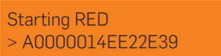
Connect the RED appliance to the power supply. Plug the power supply into the electrical outlet. The Power LED will light and the system will boot. The LCD will show the message “Starting RED” and the RED-ID.
Establishing a tunnel between the branch office and the central UTM Gateway
The RED 50 will now automatically retrieve its configuration from the Internet and establish a tunnel to your central office. After successfully establishing the tunnel, the LCD will show the message “Tunnel is up (wan1)” and either the IP address or the hostname of the UTM appliance to which the RED 50 is connected.

Controls, LED Codes and LCD messages
Controls
| Power (LED) | |
|---|---|
|
Power off |
|
Power on |
| Error | |
|---|---|
|
No error |
|
Error |
| LAN/WAN connection | |
|---|---|
|
Link established |
|
Network activity |
| LCD and keys | |
|---|---|
| LCD | Display of 2 rows x 20 characters |
| Navigation keys | 4 x keys to cycle through the LCD menu |
| Interfaces | |
|---|---|
| WAN1-WAN2, LAN1-LAN4 | 6 x 10/100/1000 Base-TX interface |
| USB 2.0 | 2 x USB 2.0 interface |
| COM | Serial console interface |
| DC IN 12 V | Power |
| Navigation keys | |
|---|---|
| ◄ | Open menu, switch from value to a menu or sub-menu entry |
| ▲▼ | Navigate between the menu entries |
| ► | Enter sub-menus and value |
The following menu entries are available
| Live-Log | ||
|---|---|---|
| WAN_Status ► | IP addresses ► | Local WAN1 IP: |
| Local WAN2 IP: | ||
| Local PPP0 IP: | ||
| UTM Hostname: | ||
| 2nd UTM Hostname: | ||
| Throughput ► | WAN1 in/out: | |
| WAN2 in/out: | ||
| Tunnel ► | WAN1->UTM WAN1: | |
| WAN1->UTM WAN2: | ||
| WAN2->UTM WAN1: | ||
| WAN2->UTM WAN2: | ||
| RED-Status ► | Device ► | ID: |
| Firmware ► | Version: | |
| Uptime: | ||
| 3G/UMTS-Status ► | Signal Strength: | |
LCD messages
| Message | Description |
|---|---|
| Booting up | The RED device is booting. |
| Shutting down | The RED device is shutting down. |
| Starting RED ID $RED_ID | The RED device is starting (the displays shows the RED ID as printed on the product label). |
| Starting RED Network Setup | The RED device is configuring DHCP or a static setup. |
| Starting RED Try $uplink | The RED device is connecting to the displayed uplink (wan1, wan2, or umts). |
| Starting RED UTM $hostname | The RED device is connecting to the UTM appliance. |
| Got new config | The RED device has received a new configuration. |
| Tunnel is up ($uplink) UTM $hostname | The RED tunnel has been established; $uplink can be wan1, wan2, or umts; $hostname can be hostname or IP address of UTM appliance. |
| ERROR Invalid device ID | The RED device has not been provisioned correctly. |
Important note: Do not unplug the power while the firmware is updating. Otherwise the RED appliance will be rendered inoperable and must be returned to the reseller.
SD-RED 20 - Quick start guide
sophos-quick-start-guide-sd-red-20.pdf
SD-RED 60 - Quick start guide
sophos-quick-start-guide-sd-red-60.pdf
Additional troubleshooting techniques
Troubleshooting static address assignments
Problem: If a RED is deployed to a location that only supports a static public IP address and the RED was not configured with a static IP through the UTM prior to shipping.
Solution:RED requires a DHCP connection with access to the Internet at least once, prior to being deployed with a static IP address. If the RED is replacing an existing firewall, and that firewall distributes DHCP addresses to internal clients, first try to connect the RED WAN port to the existing internal network. Watch the front LEDs to see that the RED connects to the Internet. It will connect to the internet, obtain its settings, then reboot. After reboot, it should fail to connect to its gateway, or to the Internet. This will indicate that it has loaded its configuration, and static IP settings.
If there is not a DHCP connection available locally, a DHCP connection to the Internet will need to be found, before the RED can be configured.
Problem: RED has been correctly configured with a static IP address, but it is not connecting to the Internet
Solution: The most straightforward method to validate that the static address settings applied to RED are valid, is to test those same settings on another device. For instance, configure the ethernet port of a laptop to use the same settings, then unplug the ethernet cable from the RED WAN port, and connect it to the laptop. Before connecting the laptop, be sure that it has a firewall enabled, and ensure that other connections such as wireless, or mobile broadband, are disabled. Once the laptop is configured and connected, both IP connectivity to the internet, as well as DNS resolution should be tested. To test these settings manually, perform the following steps:
Open a command prompt (In Windows, ÿ + r, then type “cmd.exe” and click Ok.)
First, test that the Internet is reachable. This can easily be done by “pinging“ an IP address. An easy address to test with, is Google’s public DNS servers – 8.8.8.8
Type the following command, then hit enter:
ping 8.8.8.8
If the command fails completely, it may look like this:
Pinging 8.8.8.8 with 32 bytes of data:
Request timed out.
Request timed out.
Request timed out.
Request timed out.
Ping statistics for 8.8.8.8:
Packets: Sent = 4, Received = 0, Lost = 4 (100% loss),
It is also possible that it may fail only partially. In this case, one or more of the replies may be Request timed out, as shown above. If either is true, this may be why the RED is failing, and the location’s IPS may need to be consulted to verify that the address settings are correct.
If the above test does not fail, then type
ping www.sophos.com
If it succeeds, it will resolve www.sophos.com to an IP address, then attempt to ping it.
Gathering more information
Once you are aware of the blink codes, what error code the RED is displaying, it may be useful to collect some additional information about your RED's configuration. Gather the following information from your UTM, under RED Management > Device Configuration > Edit (for the device that is not functioning correctly):
| RED ID: | |
|---|---|
| UTM Hostname: | |
| Uplink Mode: | DHCP Client – or – Static Address |
| Address: | |
| Netmask: | |
| Default Gateway: | |
| DNS Server: | |
| Operation Mode: | Standard/Unified – or – Standard/Split – or – Transparent/Split |
| Model: |
The RED model, which also indicates the hardware revision, is listed on the sticker on the bottom of the appliance.
If you need to contact Sophos Support for assistance, the above information may be useful to have ready. Also, be aware of any devices such as switches, routers or other firewalls which may sit between both endpoints, and their connections to the Internet.
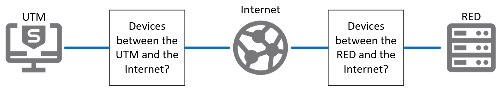
Make sure the internet type and settings of each end are recorded and available. What type of internet connection exists at the remote office? How is that connection provided to the site?
Related information
Sign up to the Sophos Support SMS Notification Service to get the latest product release information and critical issues.
Previous article ID: 116573
Uploaded SD 20 and SD 60 RED Guides
[edited by: emmosophos at 5:03 PM (GMT -7) on 24 Sep 2024]
 Quote
Quote