This discussion has been locked.
You can no longer post new replies to this discussion. If you have a question you can start a new discussion

HA Active-Active UTM

Hello,

I'm configuring 2 x UTM 430 devices in HA as an Active-Active, the HA is configured to monitor a 2 port LAG (LACP) to our Core switch.

Our Core switch is in a bonded configuration VSS (ie, there are two disparate devices that are managed and appear as a single switch), our aim with the Sophos HA is to be able to weather the loss of one of the utm without too much downtime.

What I'm unsure about, is whether all 4 ports on the core switch end should be configured in the same lag group, or should the primary and secondary UTM ports be configured to separate lag groups?


Current Configuration:
Master > Port 17 > LAG (FW_TO_CORE) > Core Switch 1 Port 10ge.1.1 (LAG.0.1)
Master > Port 18 > LAG (FW_TO_CORE) > Core Switch 1 Port 10ge.1.2 (LAG.0.1)
Slave > Port 17 > LAG (FW_TO_CORE) > Core Switch 2 Port 10ge.2.1 (LAG.0.2)
Slave > Port 18 > LAG (FW_TO_CORE) > Core Switch 2 Port 10ge.2.2 (LAG.0.2)


We have done the current configuration above and the results are:

One port on each of the Core Switch has 1 port suspended and all of the other ports are open and up. We need to make the 4 ports running and up to utilize UTMs link redundancy.

My question is that should it be 4 lag ports on 1 lag group or any other workaround for it to work properly?


Thanks in advance.

Christian


This thread was automatically locked due to age.
Parents
  • Hi, Christian, and welcome to the UTM Community!

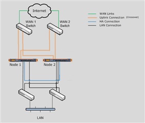
    I'm a visual-tactile learner, so I would need to diagram your situation to understand it.  How does your setup differ from the following diagram?

    Cheers - Bob

     
    Sophos UTM Community Moderator
    Sophos Certified Architect - UTM
    Sophos Certified Engineer - XG
    Gold Solution Partner since 2005
    MediaSoft, Inc. USA
Reply
  • Hi, Christian, and welcome to the UTM Community!

    I'm a visual-tactile learner, so I would need to diagram your situation to understand it.  How does your setup differ from the following diagram?

    Cheers - Bob

     
    Sophos UTM Community Moderator
    Sophos Certified Architect - UTM
    Sophos Certified Engineer - XG
    Gold Solution Partner since 2005
    MediaSoft, Inc. USA
Children
  • Hi Bob,


    Thanks for the response.


    There are just few things that differ on the provided diagram.


    1. All WAN networks are connected to one UTM, which is the Master node 1 and node 2 acts as a slave.

    2. The switches acts as one device, switches are in VSS (Virtual Switching System)


    So do we need to put all interfaces on both switches on one lacp group or different group for each switch.


    If you have more questions please don't hesitate to ask.


    Thanks,

    Chris


  • "1. All WAN networks are connected to one UTM, which is the Master node 1 and node 2 acts as a slave."

    Both Master and Slave must be cabled identically, Chris.  It's not clear to me that you would want to use LAGs.  What do you hope to achieve with them?

    Cheers - Bob

     
    Sophos UTM Community Moderator
    Sophos Certified Architect - UTM
    Sophos Certified Engineer - XG
    Gold Solution Partner since 2005
    MediaSoft, Inc. USA
  • Let me clarify if all wan networks are connected to one device. But the point of this discussion is we just want to achieve redundant links between core switch and UTM in case one FW is down all network will pass through to the other FW.

  • As I said, Chris, you don't want to use a LAG from a switch to connect it to both UTMs - just use a single connection to each as in the diagram.  Depending on your switches and their configuration and capabilities, you might want to configure LAGs on the UTMs to connect each to both switches.

    Cheers - Bob

     
    Sophos UTM Community Moderator
    Sophos Certified Architect - UTM
    Sophos Certified Engineer - XG
    Gold Solution Partner since 2005
    MediaSoft, Inc. USA
  • Hi.

    I am in the process of setting a UTM Cluster with a Cisco 6807 VSS Cluster.

    In a Failover Situation where one of the Switch clusters die. I would not want the UTM's to fail over unless theres a problem with the UTM'n!


    This can be solved by useing a MulitChase Etherchannel.


    My consern about this, is the following

    I cant find any inforamtion about how HA and LACP Operates.


    If i loose one link on the Master, and the Slave have both links intact.

    The EtherChannel would still be up on both!

    Would the HA Failover to the Slave (Because the etherchannel have more links), or would the master continiue to operate( because the Ehterchannel is up)


    Any body know how HA vil operate in this Scenario?  

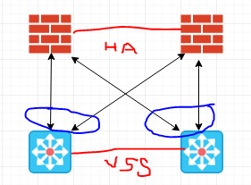
  • In Reply to you Chris.

    This is how i am planing to do it, with the knownlede i have now.

    Althoug i have the conserns raised in the Post above.


  • BrucekConvergent gave a prescription here several years ago for how to use UTM LAGs with Cisco switches.  That enables you to use a LAG to connect Master and Slave to both switches as in the Full Mesh diagram in my first post here.  Unlike Bruce, I'm not a CCIE, so I don't understand the notations on your diagram, Svein.

    Cheers - Bob

     
    Sophos UTM Community Moderator
    Sophos Certified Architect - UTM
    Sophos Certified Engineer - XG
    Gold Solution Partner since 2005
    MediaSoft, Inc. USA
  • We run 2x SG310's (active/failover) into a Cisco 3750x stack. The WAN on both SG310's are port channeled with each port on a different switch.

    If a switch or UTM fails, the other will run.