This discussion has been locked.
You can no longer post new replies to this discussion. If you have a question you can start a new discussion

SG135 C2000 BUG

Hello, I recently bought a used SG135 rev.1 which has AVR54 bug (I found out about this bug after I buy it).

For others vendors I found a possible fix, but not for Sophos.

There are two (as far as I know) fixes:

1. Replace a atom c2xxx with C0 revision

2. external pull-up resistor (18.2k to 10k), from LPC_CLKOUT0 or LPC_CLKOUT1, tied to 3.3V

Did someone tried to fix this bug? (I use home license, so I don't have any agreement with Sophos).


Best regards,

  Robert


This thread was automatically locked due to age.
Parents Reply
  • Well, more than I read more confused I am. Someone in this forum fixed LPC_CLKOUT0 with resistor 110 Ohm to 3.3V (actually my first post is not right regarding resistor, correct should be 8.2k to 10k, but this information I can't find anymore). So I'm not sure anymore. All fixes I saw are working with 100 or 110 Ohm resistor.

    So be smart ...

Children
  • Hi Guys,

    I've got a dead SG 135 that I would like to try and fix.

    Does anyone know which pins to connect the resistor? Does anyone have a picture of the workaround?

    Cheers

  • For now everything is pure speculation. Nobody know were to put resistor.

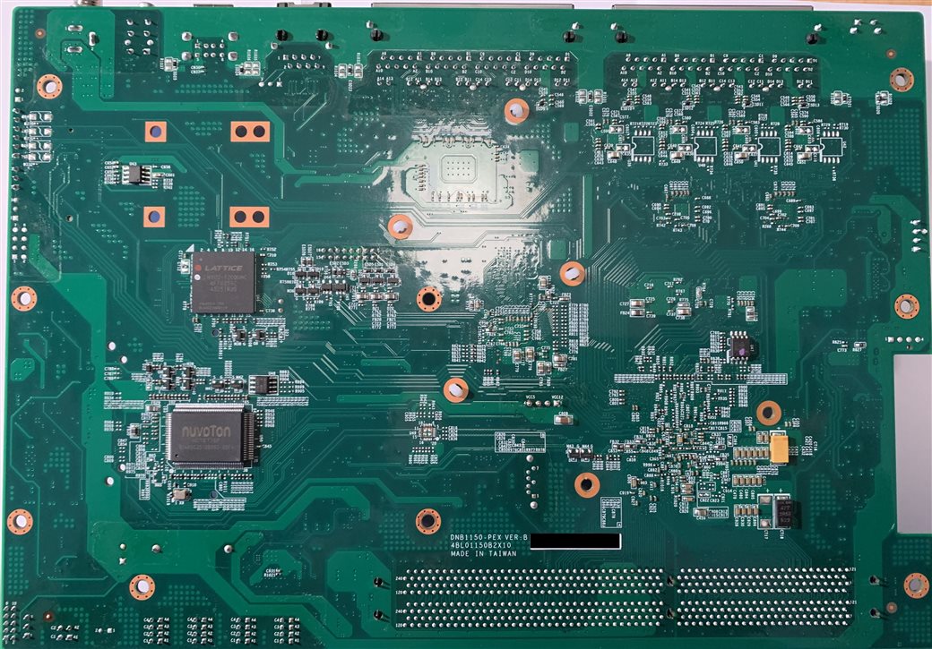
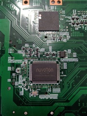
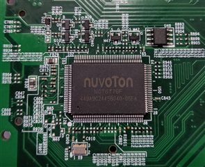
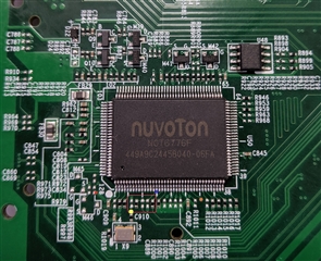
    Try an idea of Andreas. There could be LPC clock in but on the pictures is not visible if PIN15 is actually connected (need better picture of surroundings of NuvoTon NCT6776F chip).

    Did you try to remove the battery for a few minutes? 


    For now, without scheme will be very hard to tell where to put resistor!

  • Hi Robert,

    Thanks for the information. Please see the picture of the Nuvoton chip. I have tried to remove the battery and start the unit again without success.

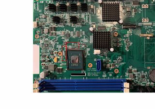
  • Hello, on this new pictures is visible, that pin 15 is connected to open pin (in fact in two open pins) and one closed pin which I think goes to C910 (yellow dot). Need better picture of red square. From yellow point it goes up on open pin then right (need better picture) to closed pin (capacitor, resistor) and then left (open) and left (open) and finally to pin 15!

    Red dot is 3.3V. Blue dot is pin15 (IOCLK) - This pin maybe wrong for fix, as is connected to 48Mhz clock???

    EDIT: C910 is connected to X9 (it provides 48MHz clock to pin15!!!). Can someone measure this???


    BTW:

       This is pure speculation and without scheme is almost impossible to say to which pin you/we should add a resistor. I'm not responsible for any way!!

  • The synology fix is straighforward because the LPC clock in question is also used (multiplexed) as GPIO, and these GPIO pins are broken out to some sort of unpopulated connector that is easy to solder.

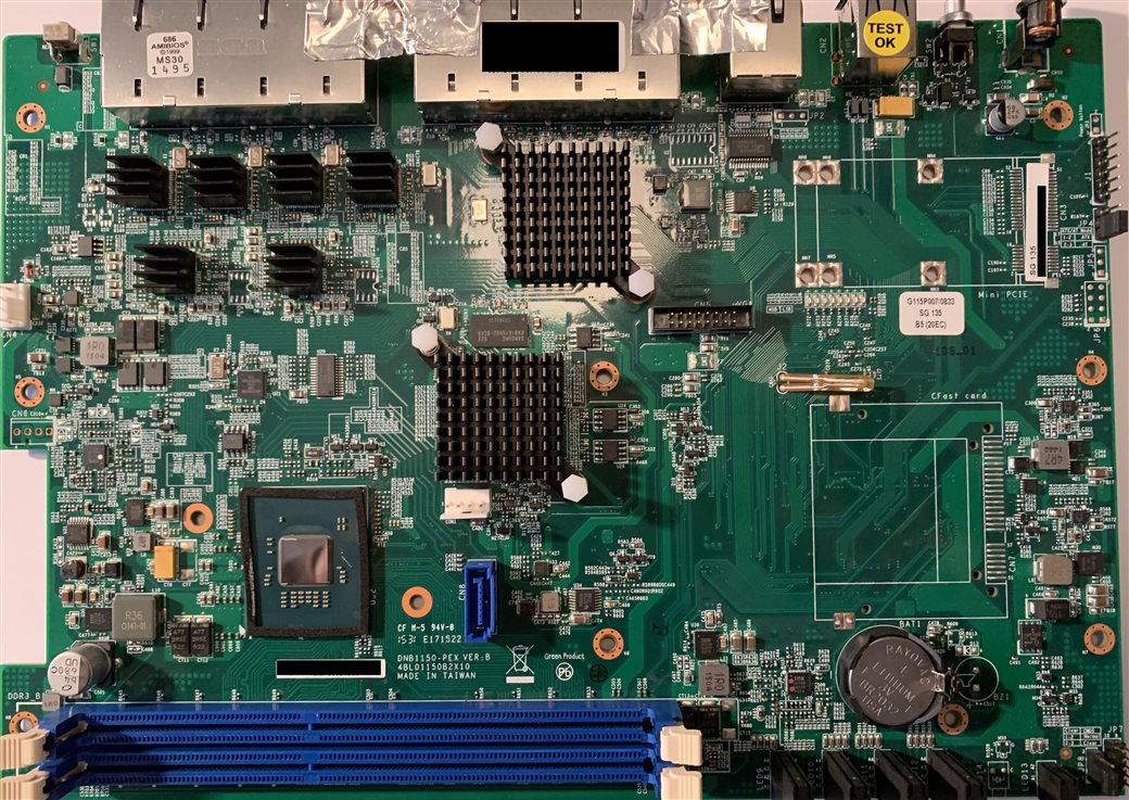
    One of the unused or unpopulated jumper blocks on the the SG125 board may also be GPIO, but JP7 is the only possible candidate I can see with enough pins, and even then it would have to use the same GPIO pins on the C2000 that are mux'd over the LPC clock pins. It should be easy enough to test though.

    Also, these are older pieces of hardware that have probably been running constantly for 4+ years, in all sorts of conditions. If you have a dead one then the C2000 bug is definitely a possibility, but there are plenty of other ways hardware can fail :) The one I am looking at right now started crashing every few days at first, then every few hours, now it won't POST. Lack of POST is definitely the defining symptom of C2000 fault (can't load BIOS from flash), but the crashing out with increasing frequency isn't, so I think my device may actually have a different fault.

    James